Asus AP140R-E1 User Manual
Page 53
4-11
ASUS AP140R-E1 1U barebone server
PSCH-LR
®
PSCH-LR J3 Connector
J3
LED-
NC
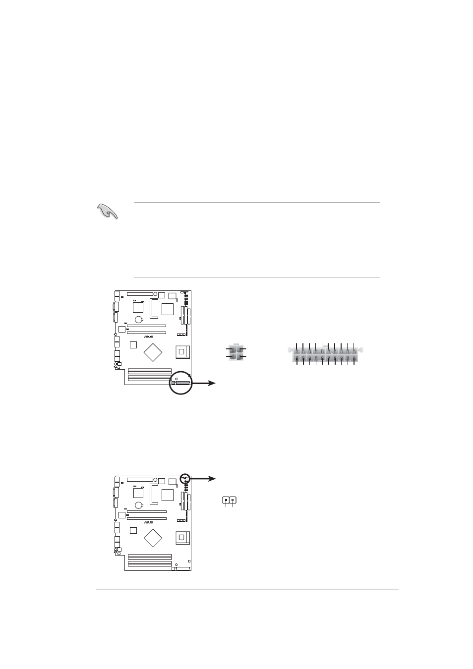
5. ATX power connectors (20-pin, 4-pin ATXPWR1)
These connectors are for the ATX power supply plugs. The plugs from
the power supply are designed to fit these connectors in only one
orientation. Find the proper orientation and push down firmly until the
connectors completely fit.
In addition to the 20-pin power connector, this motherboard requires
that you connect the 4-pin ATX +12V power plug to provide sufficient
power to the CPU.
1. Do not forget to connect the 4-pin ATX +12V power plug.
Otherwise, the system does not boot up.
2. Make sure that your ATX 12V power supply can provide 8A on the
+12V lead and at least 1A on the +5-volt standby lead (+5VSB).
The minimum recommended wattage is 300W. The system may
become unstable or may not boot up if the power is inadequate.
6. LED connector (2-pin J3)
For some storage cards, such as SCSI cards, with access signals for
external LEDs, this connector allows the access signals to go through
the front panel IDE_LED lead.
PSCH-LR
®
PSCH-LR ATX Power Connectors
ATXPWR1
ATX12V1
Pin 1
+3.3VDC
-12.0VDC
COM
PS_ON#
COM
COM
COM
-5.0VDC
+5.0VDC
+5.0VDC
PWR_OK
+12.0VDC
+3.3VDC
+3.3VDC
COM
+5.0VDC
COM
+5.0VDC
COM
+5VSB
+12V DC
GND
+12V DC
GND