Ss400 panel layout – SENA SS800 User Manual
Page 15
15
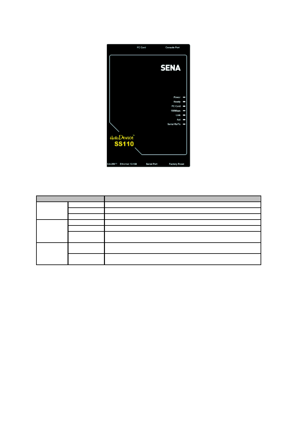
Figure 2-2 The panel layout of the SS110
Table 2-2 LED indicator lamps of the SS 110/400/800
Lamps
Function
Power
Turned on if power is supplied
Ready
Turned on if system is ready to run
System
PC card
Turned on if a PCMCIA device is running
100Mbps
Turned on if 100Base-TX connection is detected
LINK
Turned on if connected to Ethernet network
Ethernet
Act
Blink whenever there is any activities such as incoming or outgoing packets
through the Super Series Ethernet port
InUse
Turned on if the serial port is in use (SS400/800 only, Port buffering enabled
or port access in use)
Serial port
Rx/Tx
Blink whenever there is any incoming or outgoing data stream through the
serial port of the Super Series
2.1.3. SS400 Panel Layout
The SS400 has three groups of LED indicator lamps to display the status, as shown in Figure 2-3 (i.e.
System, Ethernet and Serial ports). The first three lamps on the left side indicate Power, Ready and
PCMCIA interface. The next three lamps are for Ethernet 100Mbps, Link and Act. Next lamps indicate
InUse, Receive and Transmit of the serial ports.
Table 2-2 describes the function of each LED indicator lamp. The rear panel shows the serial ports
with RJ45 connector, Ethernet port, the SS400 console port and the power socket.