C/spi interface – Rainbow Electronics MAX1386 User Manual
Page 7
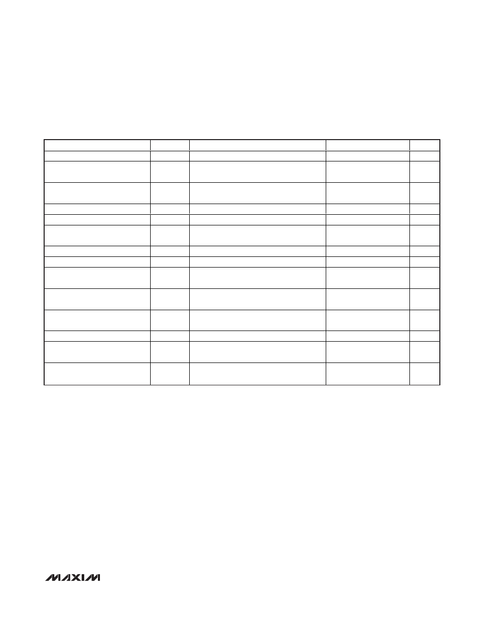
MAX1385/MAX1386
Dual RF LDMOS Bias Controllers
with I
2
C/SPI Interface
_______________________________________________________________________________________
7
I
2
C SLOW-/FAST-MODE TIMING CHARACTERISTICS (Note 12, see Figure 1)
(GATEV
DD
= +5.5V for MAX1385, GATEV
DD
= +11V for MAX1386, AV
DD
= +5V, DV
DD
= 2.7V to 5.25V, external V
REFADC
= +2.5V,
external V
REFDAC
= +2.5V, C
REF
= 0.1µF, T
A
= -40°C to +85°C, unless otherwise noted).
PARAMETER
SYMBOL
CONDITIONS
MIN
TYP
MAX
UNITS
Serial-Clock Frequency
f
SCL
0
400
kHz
Bus Free Time Between STOP
and START Condition
t
BUF
1.3
µs
Hold Time Repeated START
Condition
t
HD;STA
After this period, the first clock pulse is
generated
0.6
µs
SCL Pulse-Width Low
t
LOW
1.3
µs
SCL Pulse-Width High
t
HIGH
0.6
µs
Setup Time Repeated START
Condition
t
SU;STA
0.6
µs
Data Hold Time
t
HD;DAT
(Note 13)
0
0.9
µs
Data Setup Time
t
SU;DAT
100
ns
Rise Time of Both SDA and SCL
Signals, Receiving
t
R
(Note 14)
0
300
ns
Fall Time of Both SDA and SCL
Signals, Receiving
t
F
(Note 14)
0
300
ns
Fall Time of SDA Signal,
Transmitting
t
F
(Notes 14, 15)
20 +
0.1C
b
250
ns
Setup Time for STOP Condition
t
SU;STO
0.6
µs
Capacitive Load for Each Bus
Line
C
b
400
pF
Pulse Width of Spikes
Suppressed by the Input Filter
t
SP
(Note 16)
0
50
ns