C/spi interface – Rainbow Electronics MAX1386 User Manual
Page 40
MAX1385/MAX1386
Dual RF LDMOS Bias Controllers
with I
2
C/SPI Interface
40
______________________________________________________________________________________
2) The MAX1385/MAX1386 then transmit the contents
of the last register accessed starting with the most
significant 8-bit byte of the 16-bit word. MSBs are
sent first. Afterwards, the master needs to send an
ACK bit.
3) The MAX1385/MAX1386 transmit the least signifi-
cant 8-bit byte of the 16-bit word. MSBs are sent
first.
4) The master issues a NACK bit and then generates a
repeated START or STOP condition (Sr or P).
Poll the current register by omitting step 4 and continu-
ing to issue ACK bits after each data byte.
Stringing Commands
The MAX1385/MAX1386 allow commands to be strung
together to minimize configuration time, which is espe-
cially useful in HS mode. Figure 12 shows an example
of stringing a write and read command together to form
a write/readback command.
Figure 13 shows another useful sequence for a read-
modify-write application.
Slave Address Byte
The MAX1385/MAX1386 include a 7-bit-long slave
address. The first 4 bits (MSBs) of the slave address
are factory programmed and always 0x4h. The logic
state of the address inputs (A2, A1, and A0) determine
the 3 LSBs of the device address (see Figure 14).
Connect A2, A1, and A0 to DV
DD
or DGND. A maxi-
mum of eight MAX1385/MAX1386 devices can be con-
nected on the same bus at one time using these
address inputs.
The 8th bit of the address byte is a R/
W bit. The
address byte R/
W bit is set to 0 to notify the device that
a command byte will be written to the device next. The
address byte R/
W bit is set to 1 to notify the device that
a control byte will not be sent and to immediately send
data from the last accessed register.
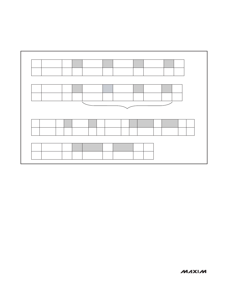
WRITE WORD FORMAT
ADDRESS
R/
W
ACK
WRITE
COMMAND
ACK
DATA
ACK
Sr OR P
7 BITS
8 BITS
0
DATA
S OR Sr
ADDRESS
ACK
Sr OR P
1
S OR Sr
ADDRESS
ACK
ACK
DATA
ACK
0
DATA
ACK
Sr OR P
ACK
ADDRESS
ACK
READ
COMMAND
ACK
Sr
ADDRESS
ACK
DATA ACK
DATA
NACK Sr OR P
1
0
DATA ACK
DATA NACK
8 BITS (MSB)
8 BITS (LSB)
WRITE BLOCK FORMAT
7 BITS
8 BITS
R/
W
WRITE
COMMAND
8 BITS (MSB)
8 BITS (LSB)
N 3-BYTE SEQUENCES (S, Sr, AND P NOT NEEDED)
8 BITS (MSB)
8 BITS (LSB)
R/
W
R/
W
7 BITS
8 BITS
7 BITS
5-BYTE READ
3-BYTE READ
R/
W
7 BITS
8 BITS (MSB)
8 BITS (LSB)
S OR Sr
S OR Sr
Figure 11. Read/Write Formats