C/spi interface, Table 27. basic software initialization, Table 26. temperature-threshold settings examples – Rainbow Electronics MAX1386 User Manual
Page 47
MAX1385/MAX1386
Dual RF LDMOS Bias Controllers
with I
2
C/SPI Interface
______________________________________________________________________________________
47
written to the Coarse DAC1/DAC2 Input Low Wiper reg-
ister. The resulting output when the low wiper is higher
than the high wiper is:
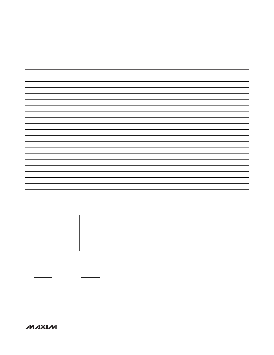
Basic Software Initialization
The MAX1385/MAX1386 do not power on all internal
blocks when full power is first applied. Software must
write to register 0x64 twice with bit D7 set to 0 during
initialization to enable full operation. A basic initializa-
tion sequence is shown in Table 27.
Regulating VGS vs. Temperature
The MAX1385/MAX1386 can be used along with a
microcontroller to perform closed-loop regulation of the
LDMOS FET bias current. For example, software can
read the temperature and use a calibrated look-up
table to determine a new value for the gate drive.
As an example, in noncontinuous conversion mode,
read temperature from remote diode 1 by writing to the
ADCCON register (0x62) with bit D1 set to 1. Wait for
BUSY to go high and then low. Read the ADC result
from the FIFO (0x80). The result bits D15–D12 = 0001
indicate the measurement source is the external tem-
perature sensor DXP1/DXN1, and bits D11–D3 indicate
two’s-complement temperature in degrees Celsius. Bits
D2, D1, and D0 are temperature subLSBs.
Gate voltage drive range must be previously deter-
mined during initialization by setting the coarse DAC1
high and low limits. Write a new value to FINETHRU1 to
immediately change the output GATE1 between the
high and low wiper limits based on the previous tem-
perature measurement.
The regulation software may also use the alarm thresh-
old limits to determine whether temperature and current
−
Ч
+
Ч
V
FINECODE
V
LOWCODE
DACREF
DACREF
2
2
18
8
COMMAND
BYTE
DATA
WORD
DESCRIPTION
0x64
0x0008
Bring the device out of shutdown mode.
0x64
0x0008
Set internal reference and both DAC channels on.
0x20
0x02A8
Set the channel 1 high-temperature threshold to +85°C.
0x22
0x0EC0
Set the channel 1 low-temperature threshold to -40°C.
0x24
0x02C1
Set the channel 1 high-current threshold to 4.3A for 50mΩ R
SENSE
, Av
PGA
= 2, and V
REFADC
= 2.5V.
0x26
0x0106
Set the channel 1 low-current threshold to 1.6A for 50mΩ R
SENSE
, Av
PGA
= 2, and V
REFADC
= 2.5V.
0x28
0x02A8
Set the channel 2 high-temperature threshold to +85°C.
0x2A
0x0EC0
Set the channel 2 low-temperature threshold to -40°C.
0x2C
0x02C1
Set the channel 2 high-current threshold to 4.3A for 50mΩ R
SENSE
, Av
PGA
= 2, and V
REFADC
= 2.5V.
0x2E
0x0106
Set the channel 2 low-current threshold to 1.6A for 50mΩ R
SENSE
, Av
PGA
= 2, and V
REFADC
= 2.5V.
0x30
0x000F
Set Av
PGA1
and Av
PGA2
to 2, clock mode to 00 and ADC/DAC references to internal.
0x32
0x0000
Set ALARM, SAFE1, and SAFE2 to depend on nothing (POR).
0x60
0x0000
Set ALARM, SAFE1, and SAFE2 for push-pull/active-high (POR).
0x74
0x00CC
Set coarse DAC1 high wiper to 204.
0x76
0x0066
Set coarse DAC1 low wiper to 102 (V
GATE
= 1.99V for MAX1385, V
GATE
= 3.98V for MAX1386).
0x7A
0x00CC
Set coarse DAC2 high wiper to 204.
0x7C
0x0066
Set coarse DAC2 low wiper to 102 (V
GATE
= 1.99V for MAX1385, V
GATE
= 3.98V for MAX1386).
0x52
0x01FF
Set fine DAC1 to midscale.
0x56
0x01FF
Set fine DAC2 to midscale.
Table 27. Basic Software Initialization
TEMPERATURE SETTING
TWO’S COMPLEMENT
-40°C
1110 1100 0000
-1.625°C
1111 1111 0011
0°C
0000 0000 0000
+27.125°C
0000 1101 1001
+105°C
0011 0100 1000
Table 26. Temperature-Threshold
Settings Examples