C/spi interface, Table 25. rdflag (read) – Rainbow Electronics MAX1386 User Manual
Page 41
MAX1385/MAX1386
Dual RF LDMOS Bias Controllers
with I
2
C/SPI Interface
______________________________________________________________________________________
41
Command Byte
The MAX1385/MAX1386 use read and write command
bytes (see Figure 15). The command byte consists of 8
bits and contains the address of the register. The com-
mand byte also communicates to the device whether a
read or write operation occurs. See the
Register
Description
section for details on how to access specif-
ic registers through the command byte.
Data Bytes
Data bytes are clocked in/out of the device with the
MSB first and the LSB last (see Figure 16). See the
Register Description
section for a description of data
bytes for each register.
Bit Transfer
One data bit is transferred during each SCL clock
cycle. The data on SDA must remain stable during the
high period of the SCL clock pulse. Changes in SDA
while SCL is high and stable are considered control
signals (see the
START and STOP Conditions
section).
Both SDA and SCL remain high when the bus is not
active. The interface can support fast (400kHz) and
high-speed (1.7MHz or 3.4MHz) data-transfer modes.
START and STOP Conditions
The master initiates a transmission with a START condi-
tion (S), which is a high-to-low transition on SDA while
SCL is high. The master terminates a transmission with
a STOP condition (P), which is a low-to-high transition
on SDA while SCL is high (Figure 17). A repeated
START condition (Sr) can be used in place of a STOP
condition to leave the bus active and the interface
transfer speed unchanged (see the
Fast/High-Speed
Modes
section).
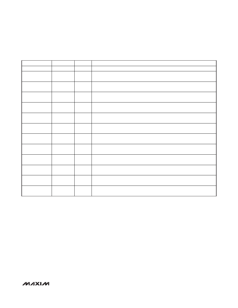
BIT NAME
DATA BIT
POR
FUNCTION
X
D15– D12
X
Don’t care
ADCBUSY
D11
0
1 = ADC is busy
0 = ADC is not busy
ALUBUSY
D10
1
1 = ALU is busy
0 = ALU is not busy
FIFOEMP
D9
0
1 = FIFO is empty
0 = FIFO is not empty
FIFOOVER
D8
0
1 = FIFO overflowed
0 = FIFO not overflowed
HIGHI2
D7
0
1 = Channel 2 high current threshold exceeded
0 = Channel 2 high current threshold not exceeded
LOWI2
D6
0
1 = Channel 2 low current threshold surpassed
0 = Channel 2 low current threshold not surpassed
HIGHT2
D5
0
1 = Channel 2 high temperature threshold exceeded
0 = Channel 2 high temperature threshold not exceeded
LOWT2
D4
0
1 = Channel 2 low temperature threshold surpassed
0 = Channel 2 low temperature threshold not surpassed
HIGHI1
D3
0
1 = Channel 1 high current threshold exceeded
0 = Channel 1 high current threshold not exceeded
LOWI1
D2
0
1 = Channel 1 low current threshold surpassed
0 = Channel 1 low current threshold not surpassed
HIGHT1
D1
0
1 = Channel 1 high temperature threshold exceeded
0 = Channel 1 high temperature threshold not exceeded
LOWT1
D0
0
1 = Channel 1 low temperature threshold surpassed
0 = Channel 1 low temperature threshold not surpassed
Table 25. RDFLAG (Read)