C/spi interface, Applications information – Rainbow Electronics MAX1386 User Manual
Page 45
MAX1385/MAX1386
Dual RF LDMOS Bias Controllers
with I
2
C/SPI Interface
______________________________________________________________________________________
45
Applications Information
ADC Clock Mode 11
See Figure 23 for an example of configuring a conver-
sion scan for internal temperature, PGAOUT1, and
ADCIN1 in clock mode 11 using the internal reference.
Timing symbols are referenced in the
Miscellaneous
Timing Characteristics
section.
See Figure 24 for an example of configuring a conver-
sion scan for ADCIN1, external temperature sensor 2,
and PGAOUT2 in clock mode 11 using the internal ref-
erence. Timing symbols are referenced in the
Miscellaneous Timing Characteristics
section.
Temperature-Threshold Examples
Table 26 shows some examples of temperature settings
in two’s-complement form.
Leap-Frogging the DACs for 18 Bits of
Resolution
Each DAC stage is configurable for leapfrog operation
by using the 8-bit coarse DACs in conjunction with the
10-bit fine DAC. Use the following procedure for setting
18 bits of resolution:
1) Write to the Coarse DAC1/DAC2 Write-Through Low
Wiper Input register (THRULO1/THRULO2)
2) Write to the Coarse DAC1/DAC2 Write-Through High
Wiper Input register (THRUHIGH1/THRUHIGH2) with
a value one higher or one lower than written to the
low wiper register.
MASTER TO SLAVE
SLAVE TO MASTER
FS MODE
FS MODE
S
MASTER CODE
A
Sr
SLAVE ADDRESS
A
COMMAND/DATA
Sr
SLAVE ADD
HS MODE CONTINUES
R/
W
FS MODE
N BYTES PLUS ACK
HS MODE CAN ALSO BE CONTINUED
WITH A COMMAND BYTE
A
P
Figure 22. Changing to FS Mode or Staying in HS Mode
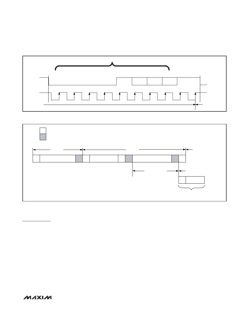
SCL
S
0
0
0
0
1
X
X
X
A
Sr
HS-MODE MASTER CODE
SDA
HS MODE
FS MODE
Figure 21. Changing to HS Mode