C/spi interface, Table 13. fine1 and fine2 (write), Table 14. finethru1 and finethru2 (write) – Rainbow Electronics MAX1386 User Manual
Page 34: Table 15. almhcfg (read/write)
MAX1385/MAX1386
Dual RF LDMOS Bias Controllers
with I
2
C/SPI Interface
34
______________________________________________________________________________________
TEXT2 to 1 to select the temperature at external diode 2
to be converted. Set ADCSEL1 to 1 to select voltages at
ADCIN1 to be converted. Set IEXT1 to 1 to select volt-
ages at PGAOUT1 to be converted. Set TEXT1 to 1 to
select the temperature at external diode 1 to be con-
verted. Set TINT to 1 to select the internal temperature
of the MAX1385/MAX1386 to be converted.
During continuous conversions (CONCONV = 1),
the ADC does not trigger the BUSY signal. When
CONCONV is set to 0, the current scan (not just the
current conversion) is completed and the ADC waits for
the next command. During continuous conversions, the
FIFO overflows if the user does not read it quickly
enough. When the FIFO overflows, it contains a mixture
of old and new conversion results (see the
RDFLAG
(Read)
section). Continuous conversion mode is only
available in clock modes 00 and 01.
SSHUT (Write)
The Software Shutdown register shuts down all internal
blocks at once or the DAC, ADC, and PGA blocks indi-
vidually. Write to the Software Shutdown register by
sending the appropriate write command byte followed
by data bits D15–D0 (see Table 17). Bits D15–D8 and
D6, D5, and D4 are don’t care.
Set FULLPD to 1 to shut down all internal blocks and
reduce the AV
DD
supply current to 0.2µA. FULLPD is
set to 1 at power-up. To change to normal power mode,
write two commands to the Software Shutdown register.
The first command sets FULLPD to 0 (other bits in the
Software Shutdown register are ignored). A second
command is needed to activate any internal blocks.
FULLPD overrides all other shutdown bits; however, all
shutdown bits retain their data when FULLPD is set to
1. This means that if DAC1 and PGA1 are shut down
before FULLPD is set to 1, they remain shut down after
FULLPD is set to 0 again.
Set FBGON to 1 to force the internal bandgap refer-
ence to be powered at all times. Set FBGON to 0 to
transfer power-down control of the internal reference to
the ADC. In the event of DAC1PD or DAC2PD being set
to 0, the internal bandgap is forced on. Set OSCPD to 1
to shut down the internal oscillator. When the oscillator
is shut down, the ADC ceases conversions and internal
PGA calibration halts. Any interface command restarts
the oscillator and allows the system to resume from
where it left off. Set DAC2PD to 1 to shut down DAC2
and PGA2. Set DAC1PD to 1 to shut down DAC1 and
PGA1. DAC1PD and DAC2PD power down the individ-
ual blocks regardless of additional commands; howev-
er, writes are still permitted to the DACs and PGAs. For
maximum accuracy, do not command a DAC calibra-
tion while a DAC is powered down or powering up.
LDAC (Write)
The Software LDAC register controls the loading of the
DAC output registers with values from DAC input regis-
ters, allowing the user to update several changes to the
DAC all at once (see Table 18). Write to the Software
LDAC register by sending the appropriate write com-
mand byte followed by data bits D15–D0. Bits D15–D6
are don’t care. Any bit set to 1 in the Software LDAC
register is immediately set to 0 thereafter.
DATA BIT
POR
FUNCTION
D15–D10
X
Don’t care.
D9–D0
00 0000 0000
10-bit fine DAC input code. D9
is the MSB.
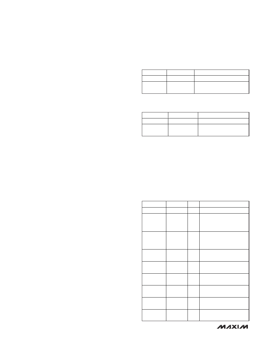
Table 13. FINE1 and FINE2 (Write)
DATA BIT
POR
FUNCTION
D15–D10
X
Don’t care.
D9–D0
00 0000 0000
10-bit fine DAC input code.
D9 is the MSB.
Table 14. FINETHRU1 and FINETHRU2
(Write)
BIT NAME
DATA BIT
POR
FUNCTION
X
D15–D8
X
Don’t care
SETSAFE1
D7
0
1 = Force SAFE1 active
immediately
0 = Normal operation
SETSAFE2
D6
0
1 = Force SAFE2 active
immediately
0 = Normal operation
ALARMPOL
D5
0
1 = ALARM is active-low
0 = ALARM is active-high
ALARMOPN
D4
0
1 = ALARM is open-drain
0 = ALARM is push-pull
SAFE1POL
D3
0
1 = SAFE1 is active-low
0 = SAFE1 is active-high
SAFE1OPN
D2
0
1 = SAFE1 is open-drain
0 = SAFE1 is push-pull
SAFE2POL
D1
0
1 = SAFE2 is active-low
0 = SAFE2 is active-high
SAFE2OPN
D0
0
1 = SAFE2 is open-drain
0 = SAFE2 is push-pull
Table 15. ALMHCFG (Read/Write)