C/spi interface, Spi digital serial interface – Rainbow Electronics MAX1386 User Manual
Page 43
MAX1385/MAX1386
Dual RF LDMOS Bias Controllers
with I
2
C/SPI Interface
______________________________________________________________________________________
43
high-speed mode (HS mode), allowing bus speeds up
to 3.4MHz. Execute the following procedure to change
from FS mode to HS mode (see Figure 21).
1) Generate a START condition (S).
2) Send byte 00001XXX (X = don’t care). The MAX1385/
MAX1386 issue a NACK bit.
3) HS mode is entered on the 10th rising clock edge.
To remain in HS mode, use repeated START conditions
(Sr) in place of the normal STOP conditions (P) (see
Figure 22). All the same write and read formats sup-
ported in FS mode are supported in HS mode (with the
replacement of repeated START conditions for STOP
conditions). Generating a STOP condition (P) while in
HS mode changes the bus speed back to FS mode.
SPI Digital Serial Interface
The MAX1385/MAX1386 feature a 4-wire SPI-compati-
ble serial interface capable of supporting data rates up
to 16MHz. Full data transfers occur in 24-bit sections.
The first 8-bit byte is a command byte (C7–C0). The
next 16 bits are data bits (D15–D0). Clock signal SCL
may idle low or high but data is always clocked in on
the rising edge of SCL (CPOL = CPHA).
Write Format
Use the following sequence to write 16 bits of data to a
MAX1385/MAX1386 register (see Figure 18):
1) Pull
CSB low to select the device.
2) Send the appropriate write command byte (see the
Command Byte
section). The command byte is
clocked in on the rising edge of SCL.
SDA
SCL
1
2
3
4
5
6
7
8
9
C6
C7
C5
C4
C3
C2
C1
C0
ACK
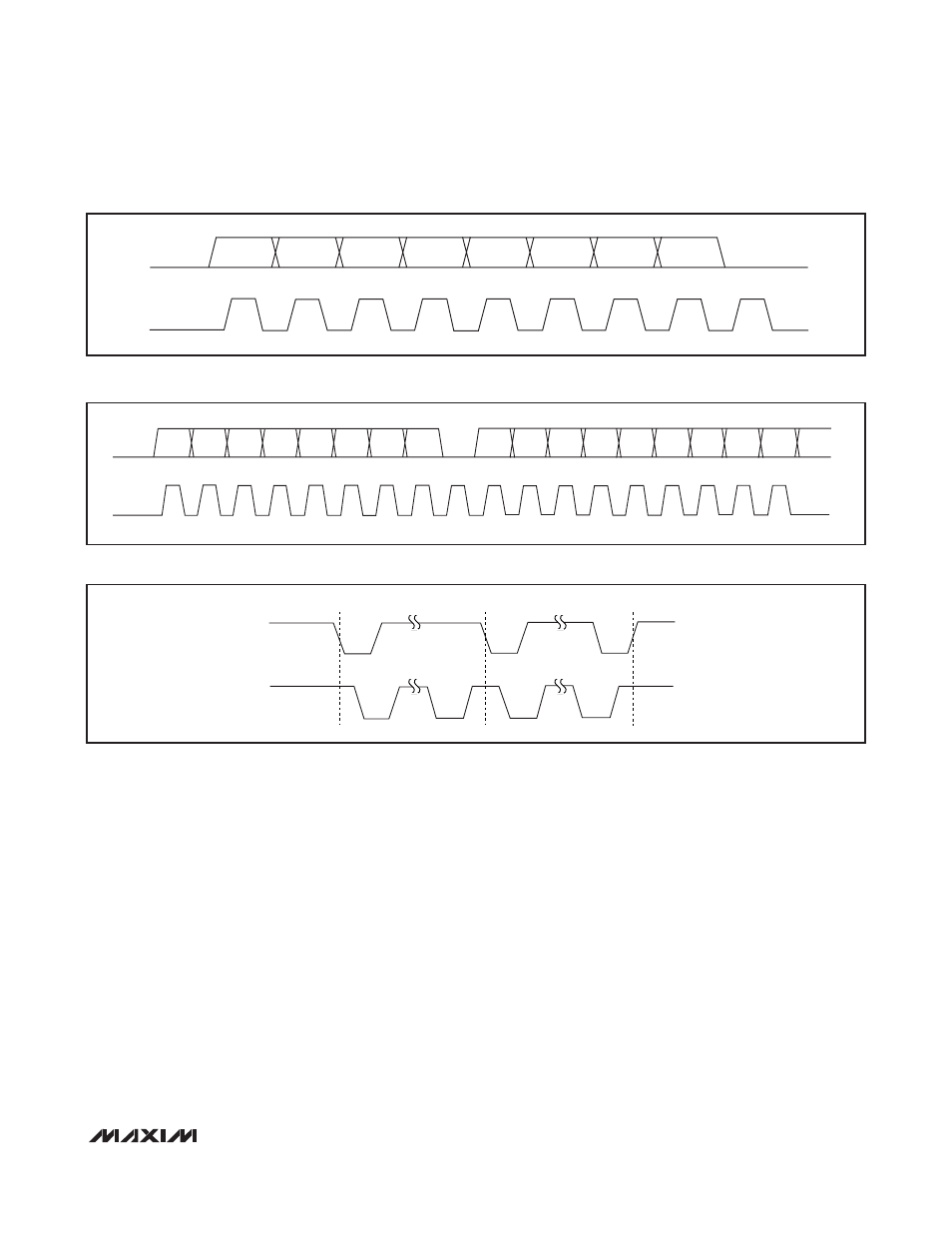
Figure 15. Command Byte
SDA
SCL
1
2
3
4
5
6
7
8
9
D14
D15
D13
D12
D11
D10
D9
D8
ACK
10
11
12
13
14
15
16
17
18
D6
D7
D5
D4
D3
D2
D1
D0
NACK
OR ACK
Figure 16. Data Bytes
SCL
SDA
S
Sr
P
Figure 17. START and STOP Conditions