Electrical characteristics, Absolute maximum ratings, Dc parameters – Rainbow Electronics T89C5121 User Manual
Page 98: Absolute maximum ratings dc parameters
98
A/T8xC5121
4164G–SCR–07/06
Electrical Characteristics
Absolute Maximum Ratings
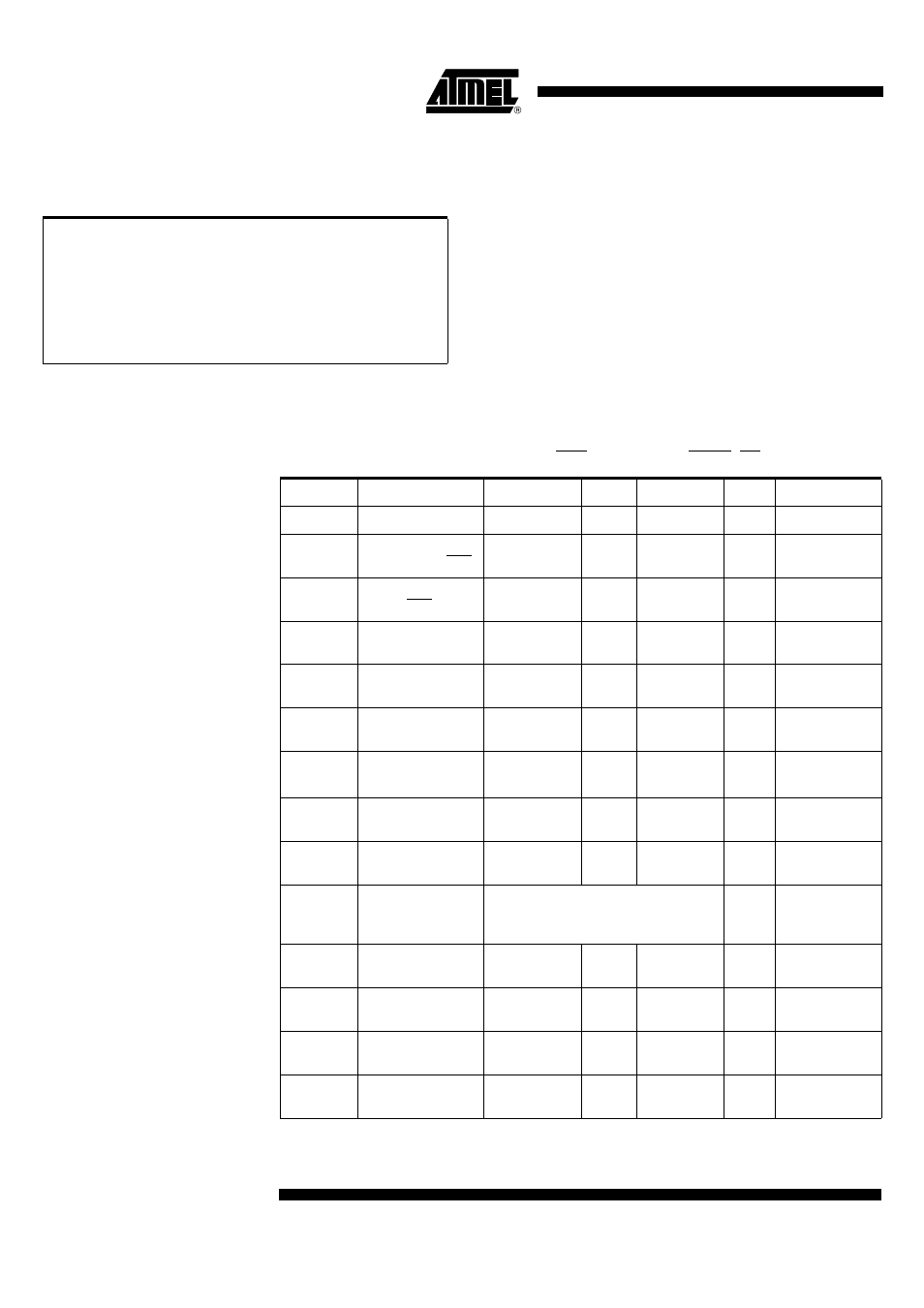
DC Parameters
T
A
= -40
°
C to +85
°
C; V
SS
= 0 V;
V
CC
= 2.85V to 5.4V; F = 7.36 to 16 MHz
Table 72. Core DC Parameters (XTAL, RST, P0, P2, ALE, PSEN, EA)
Ambiant Temperature Under Bias ......................-25
°
C to 85
°
C
Storage Temperature ................................... -65
°
C to + 150
°
C
Voltage on
V
CC
to V
SS
........................................-0.5V to + 6.0V
Voltage on Any Pin to V
SS
.......................... -0.5V to
V
CC
+ 0.5V
Note:
S
tresses at or above those listed under “ Absolute
Maximum Ratings” may cause permanent damage to
the device. This is a stress rating only and functional
operation of the device at these or any other condi-
tions above those indicated in the operational
sections of this specification is not implied. Exposure
to absolute maximum rating conditions may affect
device reliability.
Symbol
Parameter
Min
Typ
Max
Unit
Test Conditions
V
IL
Input Low Voltage
-0.5
0.2 V
CC
- 0.1
V
V
IH
Input High Voltage
except XTAL1, RST
.2 V
CC
+ .9
V
CC
+ 0.5
V
V
IH1
Input High Voltage,
XTAL1, RST
0.7 V
CC
V
CC
+ 0.5
V
V
OL
Output Low Voltage,
Port 0 and 2
0.45
V
I
OL =
1.6 mA
V
OH
Output High Voltage,
Port 0 and 2
0.9 x V
CC
V
I
OH
= -40 µA
DI
CC
Digital Supply Output
Current
6
10
mA
C
L
= 100 nF
DV
CC
Digital Supply
Voltage
2.5
2 .9
3.0
V
C
L
= 100 nF
DIcc=10mA
Icc
Normal Power Down
mode
80
100
µA
25°C
Icc
Pulsed Power Down
mode
20
30
µA
50°C Vcc=3V
Iccop
Power Supply
current
I
ccop
= 0.25 Freq (MHz) +4 mA
I
ccIDLE
= 0.03 Freq (MHz) +5 mA
V
CC
= 5.4V and
Bootloader
execution
V
PFDP
Power-fail high level
threshold
2 .55
V
V
PFDM
Power-fail low level
threshold
2
.45
V
t
G
Power Fail glitch
time
50
ns
t
rise,
t
fall
V
DD
rise and fall
time
1
μ
s
600
sec.