Bootloader functional diagram – Rainbow Electronics T89C5121 User Manual
Page 65
65
A/T8xC5121
4164G–SCR–07/06
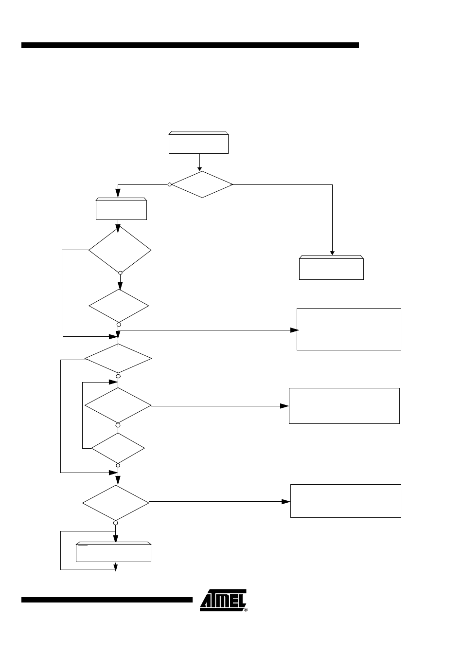
Bootloader Functional
Diagram
As described in Section “ROM Configuration Byte”, page 60a ROM bit BLJRB (Boot
Loader Jump ROM Bit) defines which product version is. The Bootloader program is
mapped in ROM space from address C000h up to FFFFh and the entry point is located
at address F800h.
Figure 27. Bootloader Flowchart
ACK?
E2PROM at 00
ACK?
E2PROM at 01
Error: No TWI or serial device detected
U Character
received on UART
?
Serial communication is detected thanks to
Time Elapsed
Internal E2PROM (at 00) is detected
Bootloader
Execution
RESET
ROM program
Execution
BLJRB = 1
ROM Bit
ROM
RAM+ROM
RAM+ROM (Pre-prod: Application Program)
F800h
versions:
ROM
ROM
0000h
External E2PROM (at 01) is detected
(Prod)
RAM,ROM,EEPROM
A serial code is sent on RD pin (P3.7)
Versions:
SSB & P3.7 test
TWI
ext.bypassed?
bypassed?
SSB & P3.6 test
UART bypassed
bypassed?
Program is downloaded from
External EEPROM into internal
An ISP Software can be used from
a PC to program the part.
Atmel FLIP software is available
Program is downloaded from
internal EEPROM in CRAM and
executed
EEPROM and CRAM
and executed.
RD port = Error code =
22h
Autobaud feature (Table52)