Sci control, Led control, Low power mode – Rainbow Electronics T89C5121 User Manual
Page 17
17
A/T8xC5121
4164G–SCR–07/06
The ports status under Power-down is the status which was valid before entering this
mode.
The INT1 interrupt is a multiplexed input (see Interrupt paragraph) with CPRES (Card
detection) and Rxd (UART Rx). So these three inputs can be used to exit from Power-
down mode. The configurations which must be set are detailed below:
•
Rxd input:
–
RXEN (ISEL.0) must be set
–
EX1 (IE0.2) must be set
–
A low level detected during more than 100 microseconds exit from Power-
down
•
CPRES input:
–
PRSEN (ISEL.1) must be set
–
EX1 (IEO.2) must be set
–
EA (IE0.7) must be set
–
In the INT1 interrupt vector, the CPLEV Bit (ISEL.7) must be inverted
and PRESIT Bit (ISEL.5) must be reset.
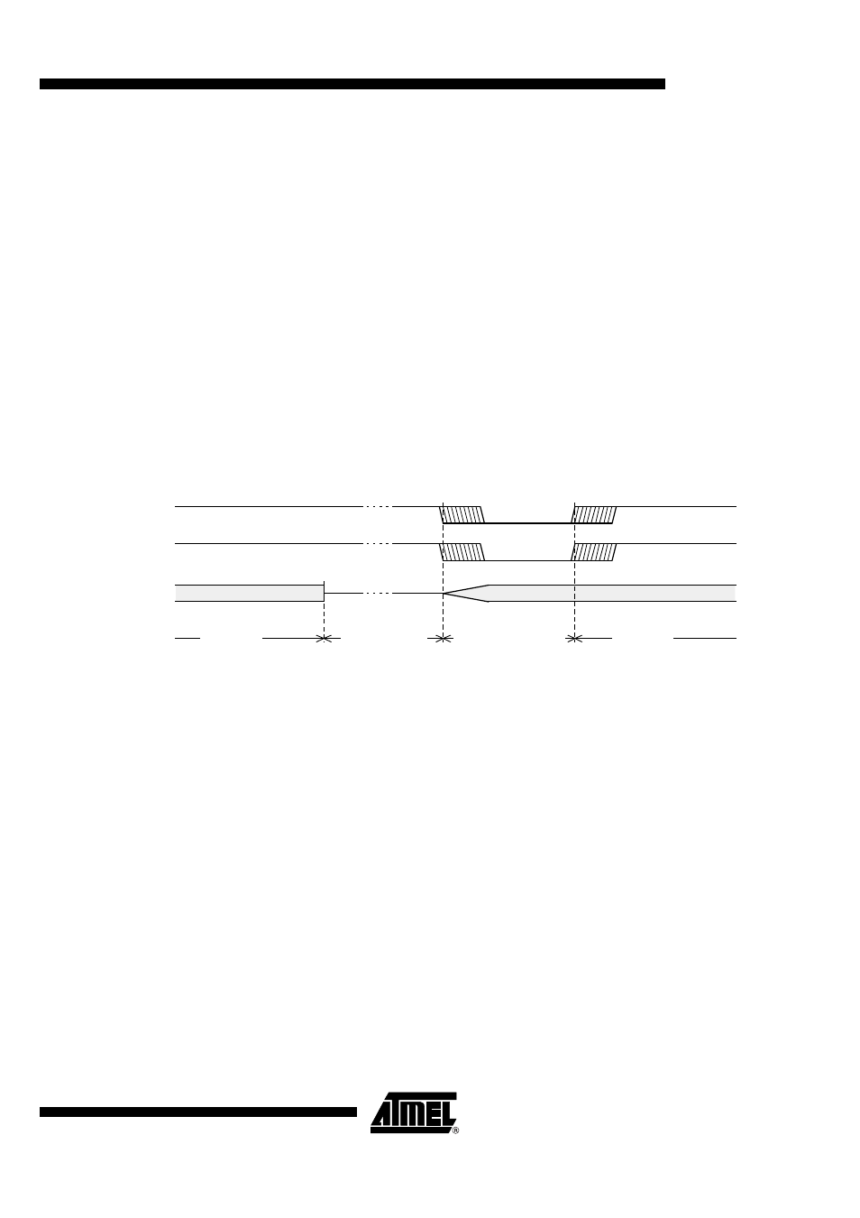
Figure 10. Power-down Exit Waveform
Exiting from Power-down by reset redefines all the SFRs, exiting from Power-down by
external interrupt does no affect the SFRs.
Exiting from Power-down by either reset or external interrupt does not affect the internal
RAM content.
Note:
If idle mode is activated with Power-down mode (IDL and PD bits set), the exit sequence
is unchanged, when execution is vectored to interrupt, PD and IDL bits are cleared and
idle mode is not entered.
SCI Control
Prior to entering Power-down mode, a de-activation of the Smart Card system must be
performed.
LED Control
Prior to entering Power-down mode, if the LED mode output is used, the medium pull-up
must be disconnected by setting the LEDPD bit in the PCON Register (PCON 3).
Low Power Mode
Only in Power-down mode, in order to reduce the power consumption, the user can
choose to select this low-power mode.
The activation reference is the following.
•
First select the Low-power mode by setting the LP bit in the AUXR Register (AUXR.
6)
•
The activation of Power-down can then be done.
INT1
INT0
XTAL1
Power-down phase
Oscillator restart phase
Active phase
Active phase