Powermonitor, Description, Powermonitor diagram – Rainbow Electronics T89C5121 User Manual
Page 14
14
A/T8xC5121
4164G–SCR–07/06
PowerMonitor
The PowerMonitor function supervises the evolution of the voltages feeding the micro-
controller, and if needed, suspends its activity when the detected value is out of
specification.
It is guaranteed to start up properly when T8xC5121 is powered up and prevents code
execution errors when the power supply becomes lower than the functional threshold.
This section describes the functions of the PowerMonitor.
Description
In order to start up and to properly maintain the microcontroller operation, V
DD
has to be
stabilized in the V
DD
operating range and the oscillator has to be stabilised with a nomi-
nal amplitude compatible with logic threshold.
This control is carried out during three phases which are the power-up, normal operation
and stop. It complies with the following requirements:
•
It guarantees an operational Reset when the microcontroller is powered
•
and a protection if the power supply goes out from the functional range of the
microcontroller.
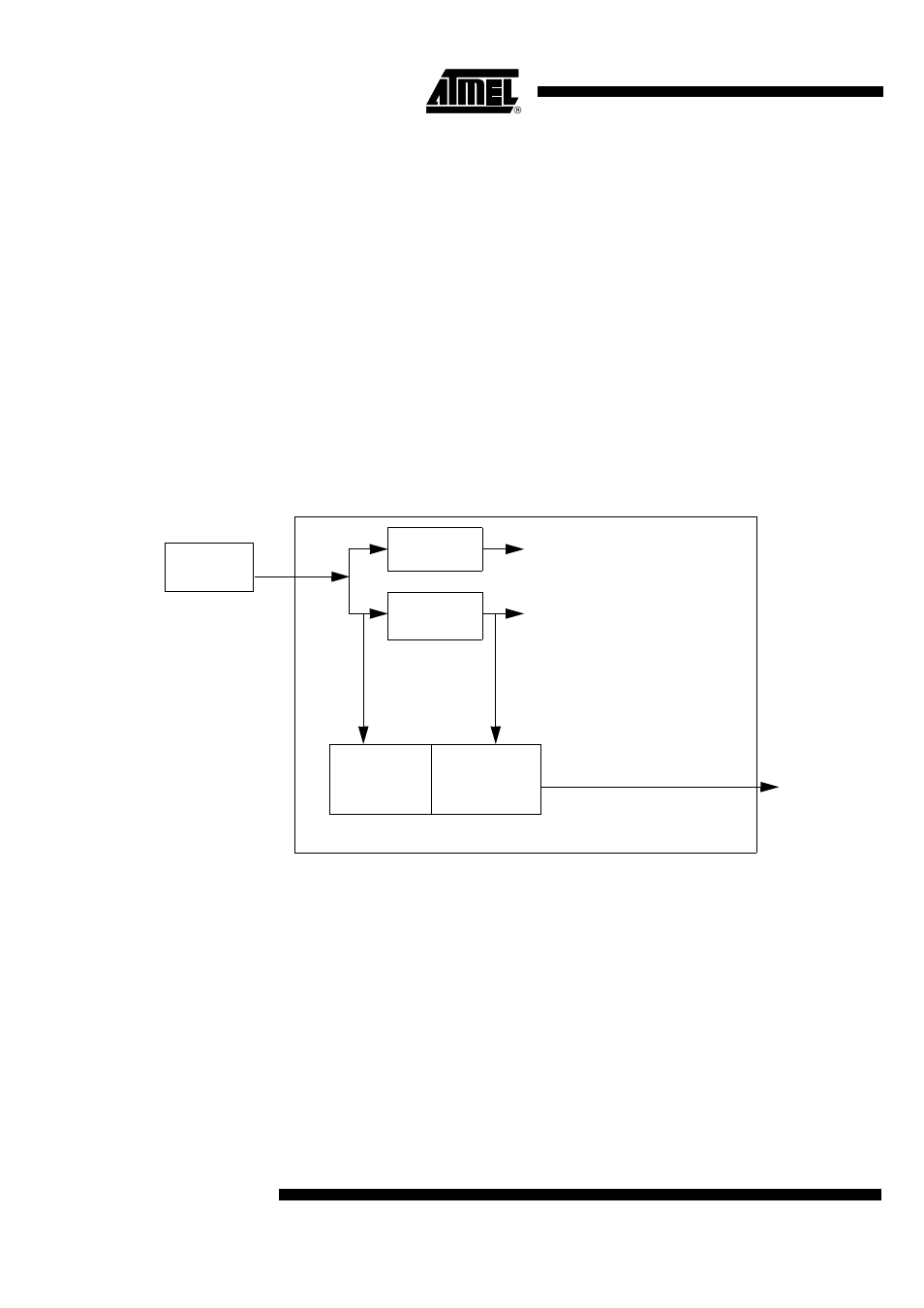
Figure 8. PowerMonitor Block Diagram
PowerMonitor Diagram
The target of the PowerMonitor is to survey the power supply in order to detect any volt-
age drops which are not in the target specification. This PowerMonitor block checks two
kind of situations that occur:
•
During the power-up condition, when V
DD
is reaching the product specification
•
During a steady-state condition, when V
DD
is stable but disturbed by any
undesirable voltage drops.
Figure 9 shows some configurations that can be met by the PowerMonitor.
External
Power Supply
DC to DC
3V Regulator
V
DD
DV
CC
CV
CC
Internal RESET
Power-fail
Detector
Power-up
Detector