Baud rate selection (mode 2), Table 65 det – Rainbow Electronics T89C5121 User Manual
Page 91
91
A/T8xC5121
4164G–SCR–07/06
Table 65. Internal Baud Rate Generator Value
Notes:
1. These frequencies are achieved in X1 mode, F
PER
= F
OSC
÷
2.
2. These frequencies are achieved in X2 mode, F
PER
= F
OSC
.
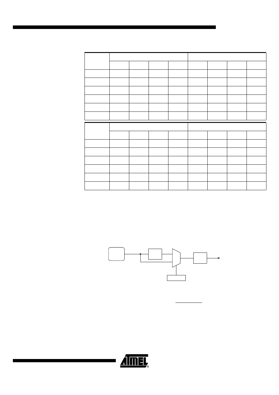
Baud Rate Selection (Mode 2)
In mode 2, the baud rate can only be programmed to two fixed values: 1/16 or 1/32 of
the peripheral clock frequency.
As shown in Figure 49, the selection is done using SMOD1 bit in PCON register.
Figure 50 gives the baud rate calculation formula depending on the selection.
Figure 49. Baud Rate Generator Selection (Mode 2)
Figure 50. Baud Rate Formula (Mode 2)
Baud Rate
F
PER
= 6 MHz
1
F
PER
= 8 MHz
1
SPD
SMOD1
BRL
Error %
SPD
SMOD1
BRL
Error %
115200
-
-
-
-
-
-
-
-
57600
-
-
-
-
1
1
247
3.55
38400
1
1
246
2.34
1
1
243
0.16
19200
1
1
236
2.34
1
1
230
0.16
9600
1
1
217
0.16
1
1
204
0.16
4800
1
1
178
0.16
1
1
152
0.16
Baud Rate
F
PER
= 12 MHz
2
F
PER
= 16 MHz
2
SPD
SMOD1
BRL
Error %
SPD
SMOD1
BRL
Error %
115200
-
-
-
-
1
1
247
3.55
57600
1
1
243
0.16
1
1
239
2.12
38400
1
1
236
2.34
1
1
230
0.16
19200
1
1
217
0.16
1
1
204
0.16
9600
1
1
178
0.16
1
1
152
0.16
4800
1
1
100
0.16
1
1
48
0.16
0
1
SMOD1
PCON.7
PER
CLOCK
³ 2
³ 16
To Serial Port
Baud_Rate =
32
2SMOD1
⋅
FPER