Uart protocol, Overview, Physical layer – Rainbow Electronics T89C5121 User Manual
Page 69: Datas and limits, Frame description
69
A/T8xC5121
4164G–SCR–07/06
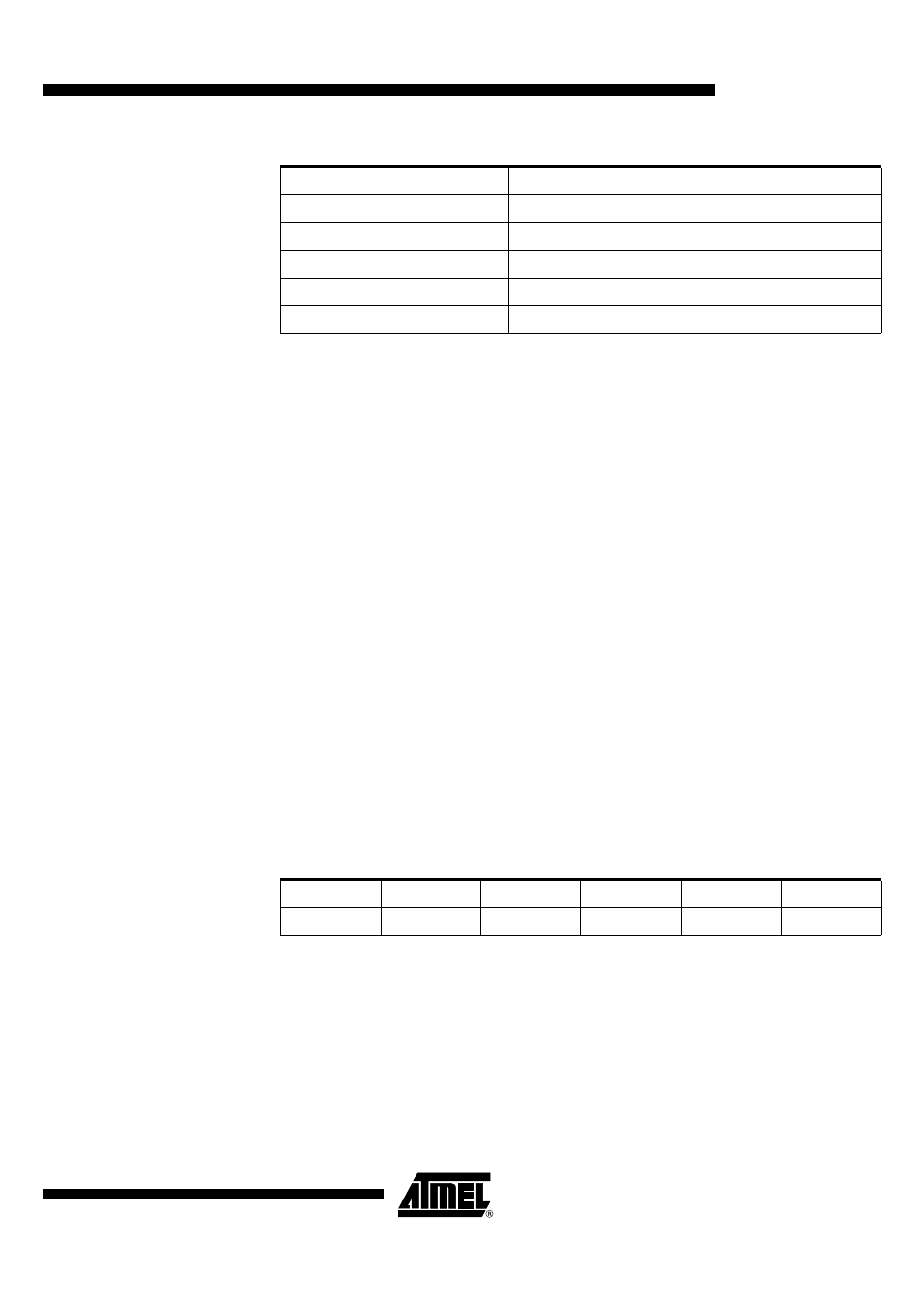
Table 49. Valid Software Security Byte Values
UART Protocol
Overview
The serial protocol used is described below.
Physical Layer
The UART is used to transmit information with the following configuration:
•
Character: 8-bit data
•
Parity: none
•
Stop: 1 bit
•
Flow control: none
•
Baudrate: autobaud is performed by the bootloader to compute the baudrate
chosen by the host.
Datas and Limits
As described in Section “Transfer Checks”, the downloaded program include the CRC
values in the last two upper bytes of the 16K bytes space.
An update of a part of the 16K program cannot be done because the CRC value would
have to be updated with a value which depends of the actual value of the rest of the
program.
So the Program function of the PC Software Tool include the individual program com-
mands (with 64 data bytes) from address 0000h to address 3FFFh.
Frame Description
The Serial Protocol is based on the Intel Hex-type records.
Intel Hex records consist of ASCII characters used to represent hexadecimal values and
are summarized below:
Table 50. Intel Hex Type Frame
•
Record Mark:
–
Record Mark is the start of frame. This field must contain’:’.
•
Reclen:
–
Reclen specifies that the number of bytes of information or data that follow
the Record Type field of the record.
•
Load Offset:
–
Load Offset specifies the 16-bit starting load offset of the data bytes,
therefore this field is used only for Program Data Record (see Table 51).
SSB Values
Functions
FE
No bypass and level1 security
FC
No bypass and level2 security
BF,BE,BC
UART bypass and security levels
7F,7E,7C
External TWI bypass and security levels
3F,3E,3C
UART and Ext. TWI bypass
Record Mark ‘:’
Reclen
Load Offset
Record Type
Data or Info
Checksum
1-byte
1-byte = 40h
2-byte
1-byte
64-byte
1-byte