Interrupt system – Rainbow Electronics T89C5121 User Manual
Page 47
47
A/T8xC5121
4164G–SCR–07/06
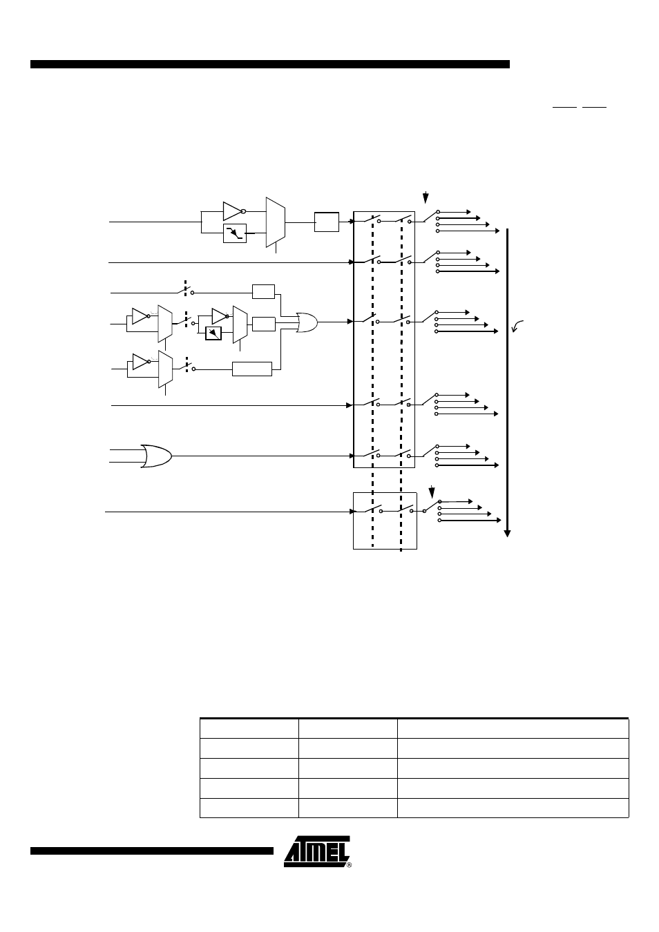
Interrupt System
The T8xC5121 has a total of 6 interrupt vectors: four external interrupts (INT0, INT1/OE,
CPRES, RxD), two Timer 0 interrupts (Timer 0s 0 and 1), serial port interrupt and Smart
Card Interface interrupt. These interrupts are shown in Figure 23.
Figure 23. Interrupt Control System
Each of the interrupt sources can be individually enabled or disabled by setting or clear-
ing a bit in the Interrupt Enable register (see Figure 32). This register also contains a
global disable bit, which must be cleared to disable all interrupts at once.
Each interrupt source can also be individually programmed to one of four priority levels
by setting or clearing a bit in the Interrupt Priority register (see Figure 36) and in the
Interrupt Priority High register (see Figure 38). Table 30 shows the bit values and priority
levels associated with each combination.
Table 30. Priority Level Bit Values
0
3
Interrupt
Polling
Sequence
TI
RI
TF0
INT0
TF1
IPH0, IPL0
IE0
0
3
0
3
0
3
0
3
0
3
Individual
Enable
Global
Enable
Low Priority
Interrupt
High Priority
Interrupt
INT1/OE
CPRES
Rxd
RXEN
SCI
RXIT
CPLEV
EX0
ET0
EX1
ET1
ES
ESCI
OEEN
0
1
IE1
1
0
0
1
PRESEN
0
1
OELEV
IT1
IT0
TCON reg.
TCON Reg.
PRESIT
The selection bits
except IT1 (TCON)
are in ISEL Reg.
IPH1, IPL1
IPH.x
IP.x
Interrupt Level Priority
0
0
0 (Lowest)
0
1
1
1
0
2
1
1
3 (Highest)