Reduced emi mode, Power modes control registers – Rainbow Electronics T89C5121 User Manual
Page 18
18
A/T8xC5121
4164G–SCR–07/06
Reduced EMI Mode
The ALE signal is used to demultiplex address and data buses on port 0 when used with
external program or data memory. Nevertheless, during internal code execution, ALE
signal is still generated.
Only in case of PLCC52 version, in order to reduce EMI, ALE signal can be disabled by
setting AO bit.
The AO bit is located in AUXR register at bit location 0 (See Table 4). As soon as AO is
set, ALE is no longer output but remains active during MOVX and MOVC instructions
and external fetches. During ALE disabling, ALE pin is weakly pulled high.
Power Modes Control
Registers
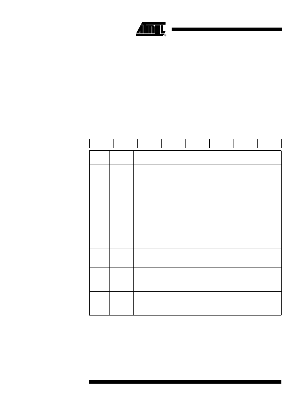
Table 3. PCON Register
PCON (S:87h)
Power Configuration Register
Reset Value = X0XX XX00b
7
6
5
4
3
2
1
0
SMOD1
SMOD0
-
-
LEDPD
GF0
PD IDL
Bit
Number
Bit
Mnemonic Description
7
SMOD1
Double Baud Rate bit
Set to double the Baud Rate when Timer 1 is used and mode 1, 2 or 3 is selected in
SCON register.
6
SMOD0
SCON Select bit
When cleared, read/write accesses to SCON.7 are to SM0 bit and read/write
accesses to SCON.6 are to SM1 bit.
When set, read/write accesses to SCON.7 are to FE bit and read/write accesses to
SCON.6 are to OVR bit. SCON is Serial Port Control register.
5
Reserved
4
Reserved
3
LEDPD
LED Control Power-Down Mode bits
When cleaned the I/O pull-up is the standard C51 pull-up control. When set the
medium pull-up is disconnected.
2
GF0
General-purpose flag 0
One use is to indicate wether an interrupt occurred during normal operation or
during Idle mode.
1
PD
Power-down Mode bit
Cleared by hardware when an interrupt or reset occurs.
Set to activate the Power-down mode.
If IDL and PD are both set, PD takes precedence.
0
IDL
Idle Mode bit
Cleared by hardware when an interrupt or reset occurs.
Set to activate the Idle mode.
If IDL and PD are both set, PD takes precedence.