Timer 0, Mode 0 (13-bit timer 0), Mode 1 (16-bit timer 0) – Rainbow Electronics T89C5121 User Manual
Page 74
74
A/T8xC5121
4164G–SCR–07/06
Timer 0
Timer 0 functions as either a Timer 0 or an event Counter in four operating modes.
Figure 28 through Figure 31 show the logic configuration of each mode.
Timer 0 is controlled by the four lower bits of the TMOD register (see Figure 56) and bits
0, 1, 4 and 5 of the TCON register (see Figure 55). The TMOD register selects the
method of Timer 0 gating (GATE0), Timer 0 or Counter operation (T/C0#) and the oper-
ating mode (M10 and M00). The TCON register provides Timer 0 control functions:
overflow flag (TF0), run control bit (TR0), interrupt flag (IE0) and interrupt type control bit
(IT0).
For normal Timer 0 operation (GATE0 = 0), setting TR0 allows TL0 to be incremented
by the selected input. Setting GATE0 and TR0 allows external pin
INT0
to control Timer 0
operation.
Timer 0 overflow (count rolls over from all 1s to all 0s) sets the TF0 flag and generates
an interrupt request.
It is important to stop the Timer 0/Counter before changing modes.
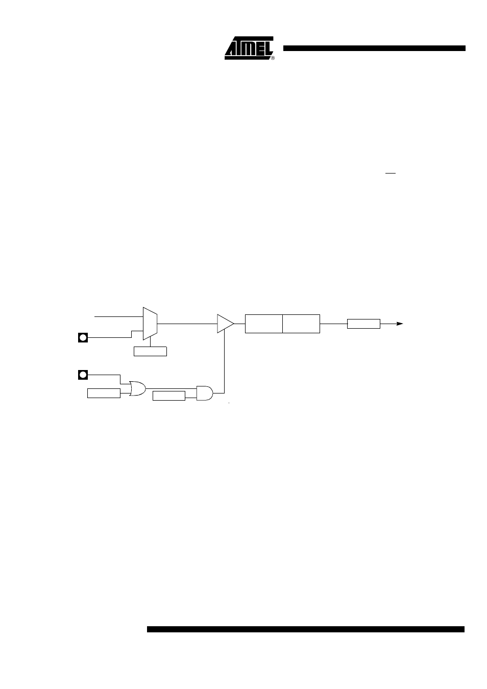
Mode 0 (13-bit Timer 0)
Mode 0 configures Timer 0 as a 13-bit Timer 0 which is set up as an 8-bit Timer 0 (TH0
register) with a module-32 prescaler implemented with the lower five bits of the TL0 reg-
ister (see Figure 28). The upper three bits of the TL0 register are indeterminate and
should be ignored. Prescaler overflow increments the TH0 register.
Figure 28. Timer 0/Counter x (x = 0 or 1) in Mode 0
Mode 1 (16-bit Timer 0)
Mode 1 configures Timer 0 as a 16-bit Timer 0 with the TH0 and TL0 registers con-
nected in a cascade (see Figure 29). The selected input increments the TL0 register.
TRx
TCON reg
TFx
TCON reg
0
1
GATEx
TMOD reg
Overflow
Timer 0 x
Interrupt
Request
C/Tx#
TMOD reg
TLx
(5 bits)
THx
(8 bits)
INTx#
Tx
FCLK_Periph