3 connection diagrams of vegapuls 64 series, Vegapuls 64 fk/dk, Vegapuls 64 fv/dv – VEGA VEGAPULS 81 User Manual
Page 50: Electrical connection, Sensors with analog 0 … 20 ma current output, Sensors with digital measuring signal
50
VEGAPULS 64 and 81
Electrical connection
VEGA PULS 64 K
8 9
4 5 6 7
I out
–(N)
VEGACONNECT
ECHOFOX
10
power supply
+ –
0/4…20 mA
service
R
ser.no.
R
–
+
+ –
+(L1)
0 … 20 mA current output
Note:
The cable diameter of the connection cables must be min.
5 mm ø and max. 10,5 mm ø. Hence the seal effect of the
cable entry will not be ensured.
Instruction:
Only carry out screening on one sensor end. Screen terminal
and earth terminal are electrically connected.
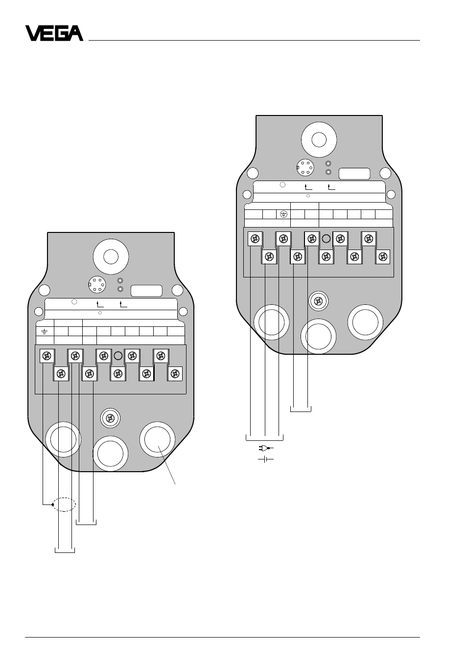
VEGAPULS 64 FK/DK
Sensors with analog 0 … 20 mA current
output
5.3 Connection diagrams of
VEGAPULS 64 series
Open the terminal box by loosening the four
screws on the upper side of the housing and
remove the yellow cover. Connect the radar
sensor acc. to the following connection dia-
gram. Take the earth/screen connection and
connect to system earth.
VEGAPULS 64 FV/DV
Sensors with digital measuring signal
VEGA PULS 64 V
8 9
4 5 6 7
VBUS
+ –
VEGACONNECT
ECHOFOX
10
407V, 509V,
512V, 514V,
571EV
service
R
ser.no.
R
+
+ –
+ –
Supply and digital
measuring signal
Optionally for external, sepa-
rate power supply
Cable entries
1 … 3 Pg 13,5