Wiring diagram for 12v led strips, Use with a velbus system – Velleman VMB1LED User Manual
Page 14
VMB1LED PWM LED strip dimmer Manual– edition 1_rev.2
14
USE WITH A VELBUS SYSTEM
The dimmer module can be part of a Velbus system and controlled by a control panel (VMB4PD) or using
pushbuttons connected to a pushbutton interface (VMB8PB).
To interconnect the Velbus modules the use of twisted-pair cable (EIB 2x2x0.8mm2, UTP 8x0.51mm - CAT5 or
equivalent) is recommended.
When a lot of modules (more than 10) are connected to the cable or longer cable lengths (more than 50m) are
used, it is important to use a cable with appropriate diameter (0.5mm² or higher).
Connect the bus to the module (beware of the polarity).
Connect the 12V to 18V direct current to the module (beware of the polarity).
A 12 or 24V direct current power supply is required for the LED strips. That power supply is completely separated
from the Velbus power supply. When connecting, make sure to use the correct polarity, as using the wrong
polarity will melt the internal fuse. The fuse can be replaced by removing the plastic power supply terminal guard.
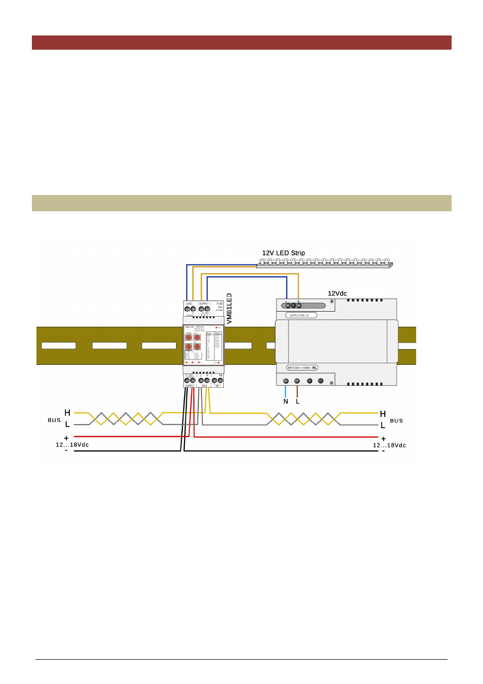
Wiring diagram for 12V LED strips
Use a 12V direct current power supply for the LED strips.
power supply