Supply connections, Pneumatic connection, Connection of the sample line – M&C TechGroup SP2600-H_C_I_BB_F_0,1GF190 Operator's manual User Manual
Page 14: Figure 5, Dismounting of the filter housing cover
14
Gas sampling and gas conditioning technology
2-1.1.5.1-ME
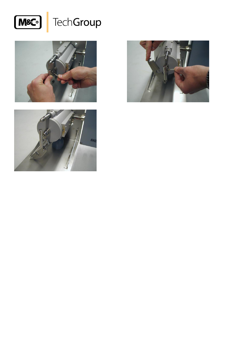
Figure 5
Dismounting of the filter housing cover
Now, the filter element is visible.
Check on the filter pressing screw whether the filter element is screwed on tightly.
Push the cover with filter element into the probe again.
Turn the clamp clip B to the right side and bring the ring bolt D into position E by using the handle
C so that the clamp clip locks into place of the ring bolt D and the threaded bolt H. For this
purpose, you may push in or pull out a little the filter housing cover by means of the straining
screw A; afterwards, turn the handle C into position F and screw the toggle handle A hand-tight by
turning to the right.
13
SUPPLY CONNECTIONS
13.1 PNEUMATIC CONNECTION
13.1.1 CONNECTION OF THE SAMPLE LINE
On the probe, a thread ¼“ NPTi is available for connecting the sample line. You can screw in
respective connection joints for lines with dimensions of Ø6mm (standard), 8mm or 10mm.
The sample line is to be mounted as follows:
Loosen the bent-lever closures of the insulating cover and remove the cover;
If you have got the 180°C version, screw the respective screws with insulating tape into
the probe head (see also 12.2);