Connection of the supply and sample lines, Figure 12 connection of supply and sample lines – M&C TechGroup SP2006-H280_DIL Operator's manual User Manual
Page 18
18
Gas sampling and gas conditioning technology
2-1.1.7.2-ME
14.1
CONNECTION OF THE SUPPLY AND SAMPLE LINES
All pneumatic lines have to be inserted through the CES cable entry, size 5, with an operative range of
36
– 70mm. It is located in the bottom of the FRP-housing. After insertion and connection of all lines
the CES cable entry can be shrinked by an air heater.
N O T E !
Increases of pressure due to use of long sample gas lines at the outlet may have a
great influence on the measuring result. For this reason, we recommend the fol-
lowing nominal widths and lengths for the sample lines in dependence on the type
of injector:
Injector type I:
i
1/4” max. 50m
i
3/8” max. 150m
Injector type II:
i
8mm max. 15m
i
10mm max. 40m
i
12mm max. 80m
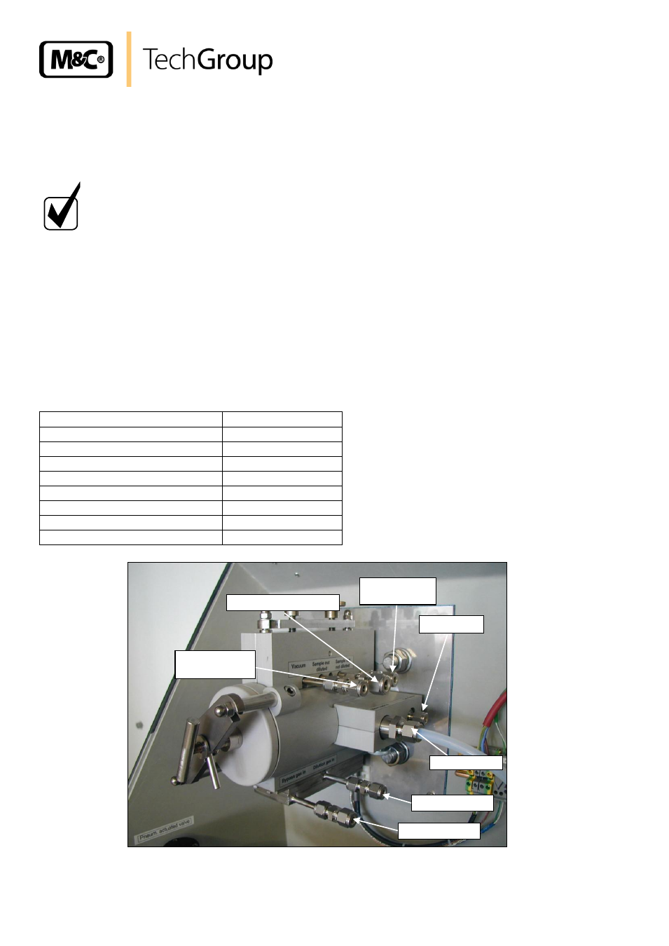
The connections for the supply and sample lines are as follows:
Connection
Dimension
Testgas In
Tube 1/4”
Dilution gas In
Tube 1/4”
Low pressure manometer
Tub
e 1/4”
Sample gas Out (diluted)
Tube 3/8”
Bypass gas In
Tube 1/4”
Bypass gas Out (diluted)
Tube 1/4”
Sample gas Out (undiluted)
Tube 1/4”
Blow back In
Tube 3/8”
Figure 12
Connection of supply and sample lines
Low pressure
manometer
Sample OUT diluted
Sample OUT
not diluted
Test gas IN
Blow back IN
Dilution gas IN
Bypass gas IN