Mounting of the probe, Checking the filter element – M&C TechGroup SP2006-H280_DIL Operator's manual User Manual
Page 16
16
Gas sampling and gas conditioning technology
2-1.1.7.2-ME
N O T E !
The dilution probe must be checked for its suitability for use with the avail-
able operating parameters prior to installation (see type plate).
13.2
MOUNTING OF THE PREFILTER RESPECTIVELY THE SAMPLE TUBE
The pre-filter or sample tube is mounted together with a suitable sealing by screwing into the
G ¾“ thread of the probe flange.
13.3
MOUNTING OF THE PROBE
Put the flange sealing on the bleeder connection.
Fit the mounting piece and the probe flange by means of the attached screws and/or screw nuts.
N O T E !
It is recommended to mount the probe with its sample gas outlet showing
downwards (not necessary for perfect function).
Further it is recommended to mount the probe with a slight descending gra-
dient downwards so that possible deposited drops may flow back into the
process.
13.4
CHECKING THE FILTER ELEMENT
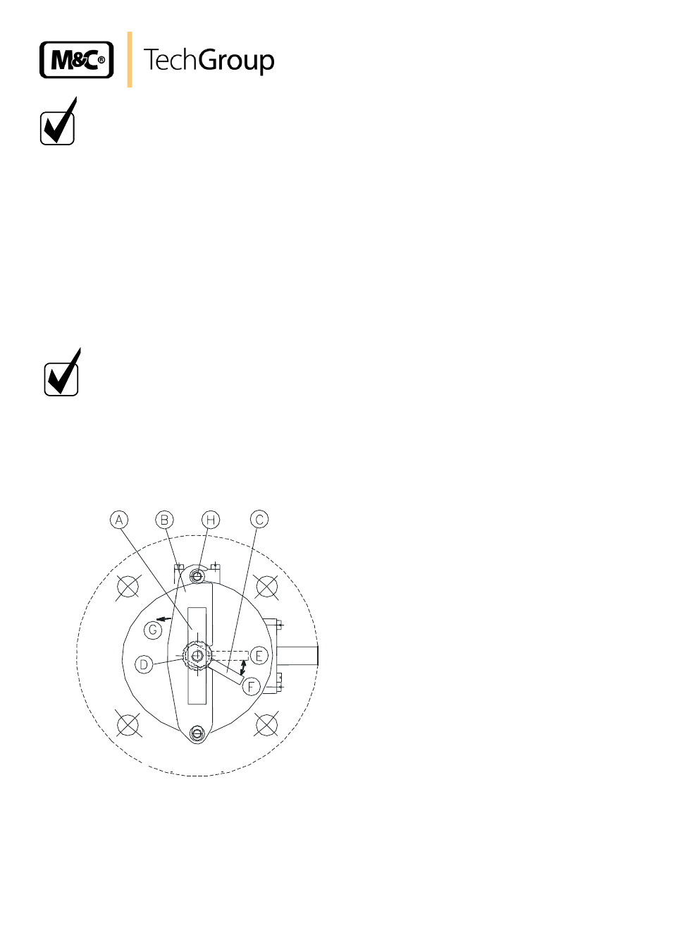
The filter housing cover is dismounted as follows:
Figure 10
Schematic drawing of the filter housing cover
Turn the toggle handle A approximately one rotation to the left side so that the cover is lifted;
Put the handle C into position E;