Mounting, Installation information, Figure 8 – M&C TechGroup SP2006-H280_DIL Operator's manual User Manual
Page 15: Construction and dimensions of the sp2006, Figure 9, Dimensions control panel -s or -s1, 13 mounting, 1 installation information
15
Gas sampling and gas conditioning technology
2-1.1.7.2-ME
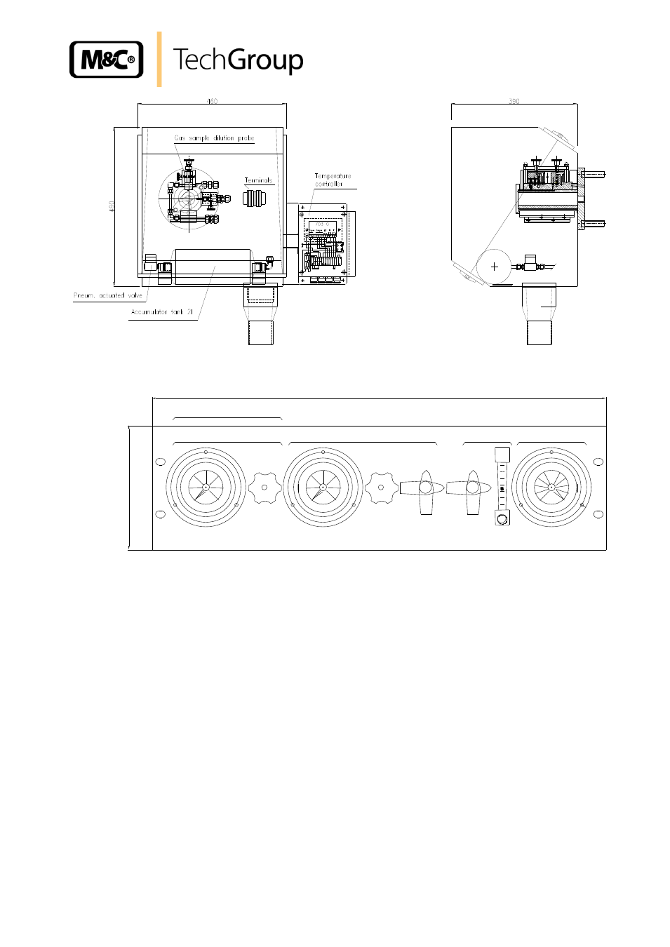
Figure 8
Construction and dimensions of the SP2006-
H…
open
482
(84TE)
132 (3HE)
Option: Bypass
1,0
0,0
6,0
5,0
Bypass-Injector
3,0
2,0
4,0
Control panel
Dilution gas
1,0
0,0
6,0
5,0
3,0
2,0
4,0
open
-0,4
0,0
Injector
Depression
-1,0
-0,8
Test gas
-0,6
-0,2
Figure 9
Dimensions control panel -S or -S1
13
MOUNTING
The M&C probes SP2006-H.. are designed for stationary use and provide a long service life and a
minimum of maintenance work under the premise of professional selection of the sampling point and
professional mounting.
13.1
INSTALLATION INFORMATION
The safety rules and regulations for the prevention of accidents must be observed during installation
and also subsequent operation. The information in chapter 3 “Safety Instructions“ must be observed.
The following also applies:
Select the optimum sampling point according to the generally applicable directives or coordinate
with the responsible departments.