M&C TechGroup SP3200 Operator's manual User Manual
Page 18
18
Gas sampling and gas conditioning technology
2-1.3.9-ME
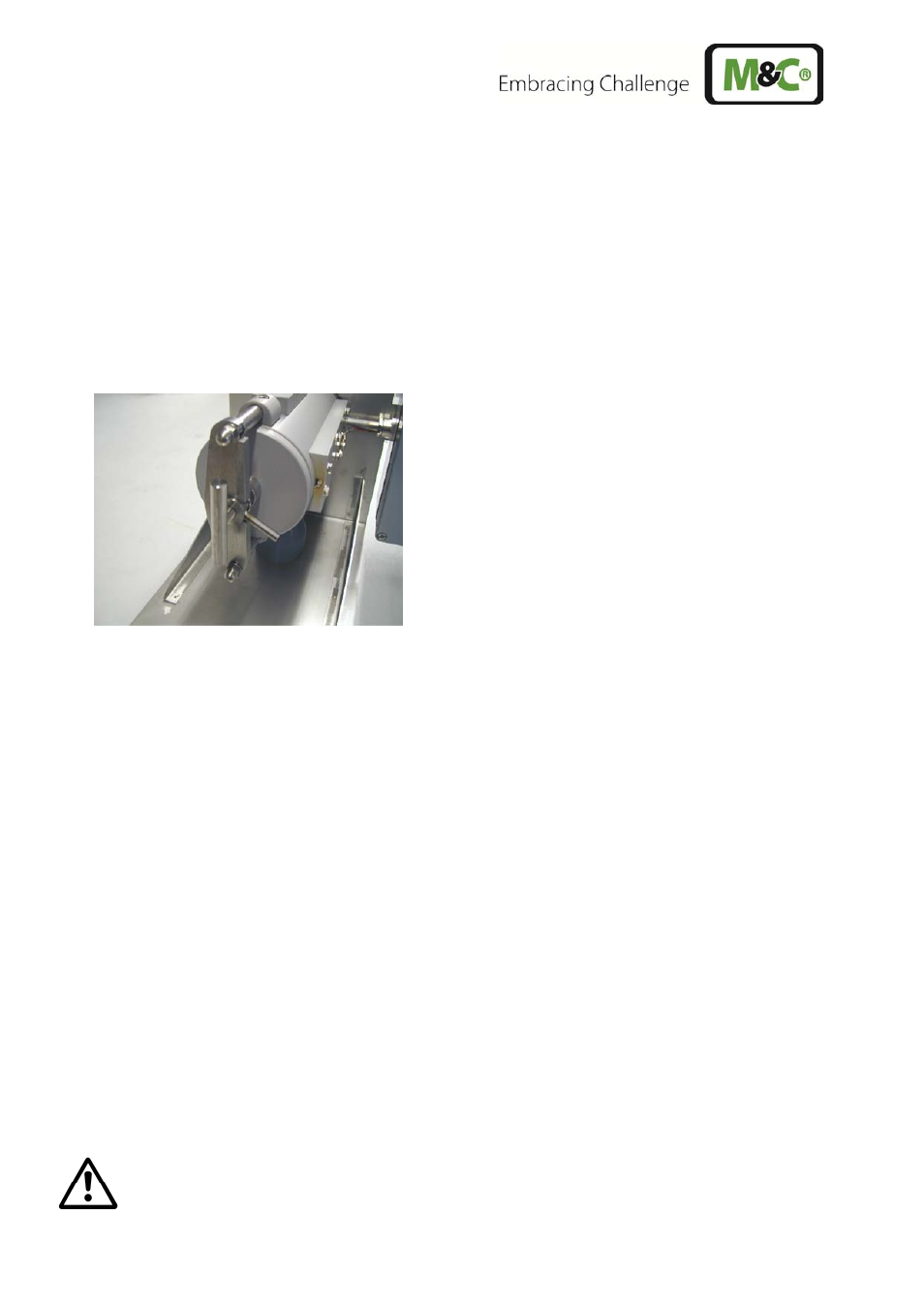
Figure 5
Removal of the filter housing cover
Check that the filter element is screwed on firmly.
Insert the filter holder part again.
The filter holder part is closed in reverse order.
Push the ¾" flat gasket on to the thread of the preliminary filter or extension tube, screw the filter or
tube into the ¾” internal thread in the flange and tighten.
If the sample nozzle does not match with the size of the standard flange connection DN65 PN6, mount the
optional flange adapter attached to the consignment on to the probe in the same way.
Place the flange gasket on to the sample nozzle.
Insert the complete probe unit into the process-side sample nozzle and screw tight with the nuts and
bolts delivered.
12.1 CONNECTION OF THE SAMPLE LINE
A ¼” NPT internal thread is provided on the probe side for connection of the sample line. Suitable con-
necting unions for explosion-protected lines in the sizes Ø 6 mm (standard), 8 mm or 10 mm can be
screwed into this thread using PTFE sealing tape.
The fittings must be tightened carefully to avoid damaging the internal components. The fit-
tings must not be overtightened.
In case of leaks, do not tighten the fittings further. Instead, the relevant fitting should be re-