M&C TechGroup SP3200 Operator's manual User Manual
Page 12
12
Gas sampling and gas conditioning technology
2-1.3.9-ME
8.11 PROBE HEATING
The probe heating type HEX5-x.08 is suitable for temperature ranges of 85°C -185°C. It consists of a heating
plate with heating cartridges and a control electronic.
For the heater type HEX5.1.08, the control electronic is mounted onto the probe. This means a range of the
ambient temperature for the probe of 0 – 50°C.
The probe heating type HEX5.2.08 is designed for an external mounting of the control unit (in Ex zone 2). For
the electrical connection, a terminal box is mounted on the probe which means an ambient temperature
range of 0 – 70°C. The externally mounted control unit can be used within an ambient temperature range of
0 – 50°C.
Technical data may be taken from the separate operating manual HEX5-x.08.
9
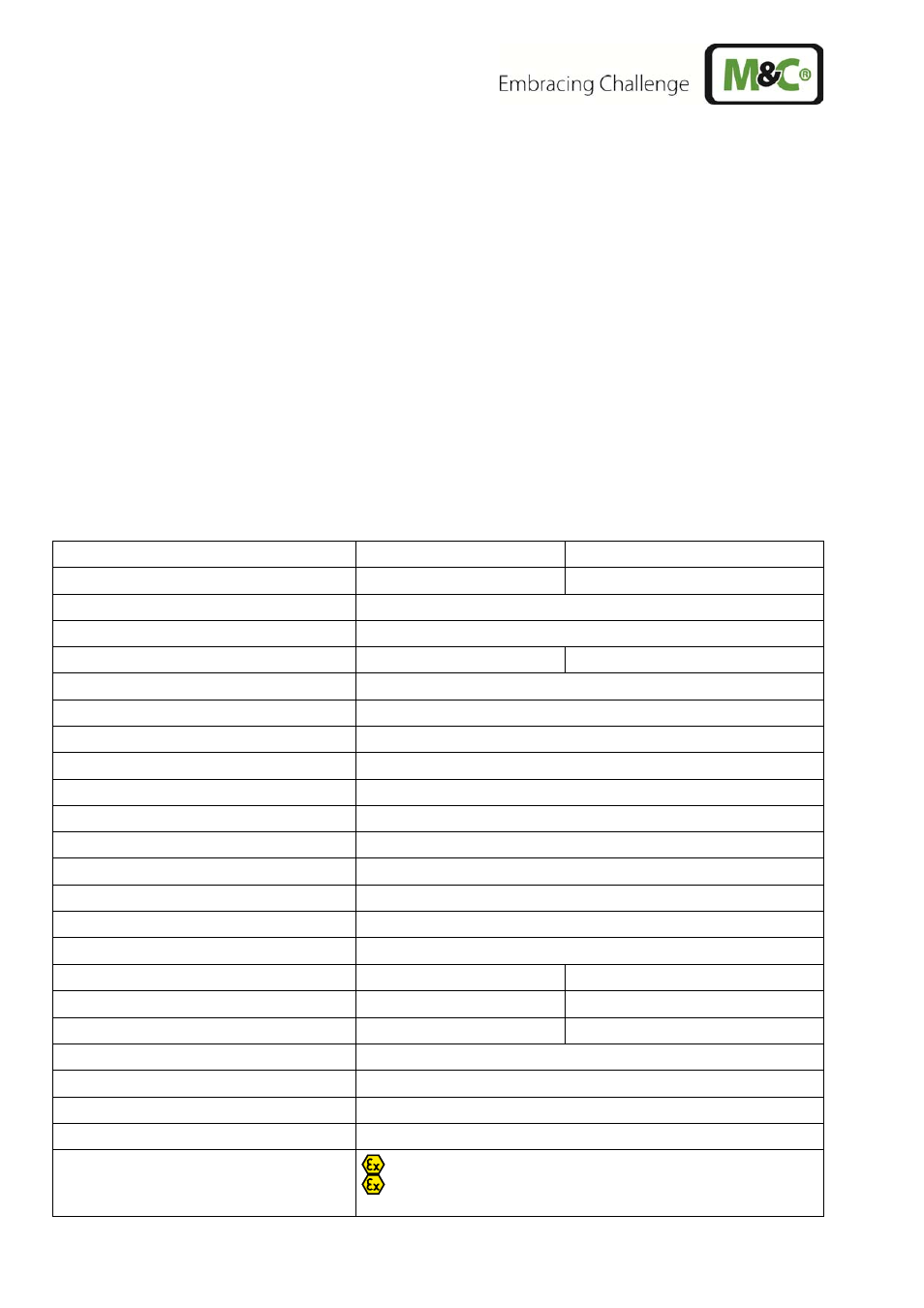
TECHNICAL DATA
Gas sample probe type
SP3200V (up to 185 °C)
SP3200 (more than 185 °C)
Part No.
20S5705
20S5700
Weather protection shield
yes
Filter housing material
Stainless steel 316 / 316Ti
Sealing materials
Graphite, FPM
Graphite
Probe flange sealing material
Graphite
Pre-filter / sample tubes
optional, see data sheet 2-1.1.0.6 and 2-1.1.0.8
Sample pressure max.
0,5-6 bar
Ambient temperature
-20 °C to max. 200 °C depending on the temperature class
Permissible process gas temperature
depending on the temperature class, however max. 200°C at the probe entry
Filter chamber volume
120 cm
3
Filter element, porosity
F-3SS150= stainless steel*, 3 micron S-2K150= ceramic**, 2 micron
Sample gas outlet connection
1x 1/4“ NPTi for max. 8mm-tube connectors
Connection gas outlet at option RS
6 mm Swagelok connector
Mounting flange
DN65 PN6, FormB, SS316Ti* >DN or ANSI possible**
Weight 7
kg
Option heating type HEX5
HEX5-1.08
HEX5-2.08
Part No.
20S9650 (a)
20S9655 (a)
Temperature controller
integrated (on the probe)
externally
Mounting controller
in the Ex-zone 2 and 22
Control electronic
Power supply
240V 50/60Hz max. 800W, alternatively 120V,50/60Hz max. 830W
Electrical connection
cable gland, terminal range 6-12mm, terminals max. 4mm
2
Marking
II 3 G Ex nA nC nL IIC T5 to T2,
II 3 D Ex tD A22 IP65 T75°C to T235°C
Class I, Division 2, Groups A/B/C/D, T5 - T2B