Linear error compensation – ACU-RITE VRO 300T User Manual
Page 43
Setup
VRO 300T
36
Linear Error Compensation
The
VRO 300T
includes a linear error compensation feature that enables you
to compensate for machine tool inaccuracies. You can have up to 99 different
compensation segments per encoder.
In order for linear error compensation to function properly, the readout needs
to be able to establish the segment boundaries in the same physical locations
each time you turn on the readout. This means that you must find the
encoder’s reference mark. Refer to page 6, “Power-On Position Recovery”.
To begin the process, select
ERROR COMPENSATION
from the
JOB SETUP
list.
Error compensation is applied to each encoder individually, so you must first
select the axis that you want to work with. You may use a display axis key
(
X
for example) to select the encoder, unless the encoder is coupled with
another one, or the encoder is displayed as the U or V axis. If that is the case,
enter the number of the input that the encoder is connected to.
Once you have selected the encoder, the readout displays the error
compensation table for that encoder. Initially, there is only one segment
defined, and it applies from one end of the encoder to the other.
The following softkeys let you begin defining the table.
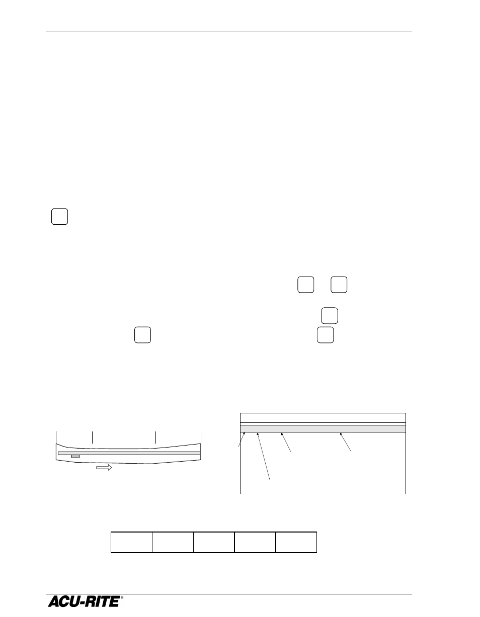
Segment 2
Segment 1
Segment 3
Machine bed side view
(slightly exaggerated)
+ Count Direction
Examples:
•
X axis displays encoder 1; you may press
X
or
1
to select this encoder.
•
Z1 axis displays encoders 2 + 3; you may press
Z1
or
2
to select encoder 2, but you must press
3
to
select encoder 3.
01 0 PPM ENCODER END - ENCODER END
ENCODER 1 ERROR COMPENSATION
Segment
number
Compensation
factor in parts
per million
Most negative
segment boundary
Most positive
segment boundary
ENTER
COMP
CALCULATE
COMP
ANCHOR
SEGMENT 1
DONE