En + drawings, Kl fall arrest, Mrope access – Petzl NAVAHO SIT FAST User Manual
Page 7: Diagram 10. how to put the harness on, Stop
7
NAVAHO SIT / NAVAHO SIT FAST / TOP / TOP CROLL C79502-C (200907)
3,0 Nm
Clic
!
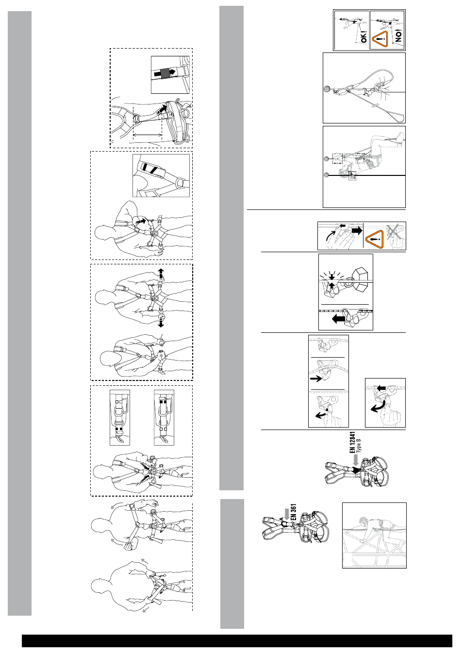
Adjustment and suspension test Your harness must be adjusted to fit snugly to reduce the risk of injur
y in case of a fall.
You must move around and hang in the harness (suspension test) from each attachment point with your equipment to verify that the harness fits properly
, provides
adequate comfort for the intended use and that it is optimally adjusted.
10F
. Initial dorsal adjustment
This adjustment should be done only once when putting on your harness for the first time. Have another person help you do it.
Slide the strap retainer so that both layers of webbing are taut between the two
buckles, (2)
and
(9)
(no slack).
Be sure to neatly stow the excess webbing (flat
-
no loops of slack) in the
strap retainer so that it doesn’t inter
fere
with your work.
Adjust the position to suit your individual body shape and size, position the
DoubleBack
buckle
at
the
level
of
the
shoulder blades.
10E. Adjust the shoulder straps. Stow the excess webbing using the strap retainer on the shoulder strap.
10D. Fasten the F
AST buckles and adjust the leg loops. Be careful of
foreign bodies which can impede the operation of the F
AST buckles
(such as pebbles, sand, clothing...). Check for correct locking.
10C. Adjust the belt by pulling on the belt straps. Stow the excess webbing neatly using the strap retainers (flat against the waist belt).
10B. Position the shoulder straps on the shoulders.
10A. Spread the shoulder straps apart, grasp the harness by the belt and slip both feet through the leg loops.
Diagram
10. How to put the harness on
Open the F
AST buckles on the leg loops.
- Short ends: use the retainers in front of the adjustment buckles.
- Long ends: pass them through the lateral rings then through the retainers behind the rings.
10A.
10B.
10C.
10D.
10E.
10F
.
K
L
FALL ARREST
Full body harness for fall arrest, component of a fall arrest system in accordance with the EN
363
standard (personal fall arrest systems). It must be used in conjunction with EN
795 anchors,
EN
362 locking carabiners, EN
355
energy absorber
, etc.
11A. Sternal attachment point Use only this point to attach a fall arrest system (for example a mobile fall arrester
, an energy
absorber
, or other system
described in the EN
363 standard).
For ease of identification, this point is marked with the letter
‘A
’.
Clearance: amount of free space below the user The clearance below the user must be sufficient to prevent the user from striking any obstacle in case of a fall. Specific details on calculating clearance are found in the technical notices for the other components (energy absorbers, mobile fall arrester
, etc.).
ASAP EN 353.2
ABSORBICA-I EN 355
Etc..
.
Fall arrest systems Example:
11A.
ASAP
EN 353.2
Diagram
11.
EN
361:
2002 fall
arrest harness
M
ROPE ACCESS
CROLL ventral rope clamp EN
12841:
2006
Field of application
The EN
12841:
2006 CROLL
rope clamp is a type
B rope
adjuster used to ascend the work rope.
ATTENTION, it must be used with a type
A backup device
on a second (safety) rope (e.g. ASAP mobile fall arrester for rope).
The CROLL ventral rope clamp is not suitable for use in an EN
363 fall arrest system.
Rope diameter
Use a 10-13
mm EN
1891
type
A semi-static kernmantel
rope.
STOP!
1
2
3
Removing the rope Move the device up the rope while pulling the trigger/safety catch down and out.
STOP!
1
2
STOP!
1
2
13C. Operational check Before each use, to verify correct orientation on the rope and functioning of the device, a test must always be carried out with the user self-belayed.
Push the CROLL up the rope. It must slide easily up the rope. Pull it down to verify it grips the rope. 13D. Precautions - Close the CROLL
’s cam when not
in use because equipment or other objects can become stuck in the device if left open.
- A
TTENTION, do not allow foreign
objects to inter
fere with the operation
of the cam (pebbles, mud, vegetation, cordage, slings, clothing, paint, etc.).
- BEW
ARE of catching the safety
catch in clothing and webbing.
- The rope between the CROLL and the anchor point must always be taut. The user must always stay below the anchor point of the rope.
- Shock-load absorption by the rope:
do not forget that it is the rope which absorbs energy in the event of a fall. The closer you get to the anchor point, the more the energy-absorbing capacity of the rope diminishes, eventually becoming practically zero.
- Protect the rope from anything
capable of damaging it (e.g. sharp edge, rough sur
face, etc).
- The rope must be able to slide freely through the CROLL. Beware of situations that can impede sliding (e.g. knot or worn/damaged section in the rope, etc.).
- Do not forget to tie a stopper knot in the end of the rope.
13B. Moving the CROLL down the rope (exceptional situation) Move the CROLL a short distance up the rope and simultaneously push down on the cam with the index finger to disengage the teeth from the sheath of the rope. Do not manipulate the trigger/safety catch because this creates a risk of involuntar
y
opening of the cam.
Diagram
13. Principles of
operation
13A. Ascending The CROLL is a device for ascending the work or access rope. It grips the rope when loaded in a downward direction and slides easily when moved up the rope.
The teeth push into the sheath of the rope, engaging the cam and causing the device to jam on the rope. Slots in the cam allow mud, etc. to be evacuated.
Diagram
14. Rope climbing
- W
ork rope: Use the CROLL and
another hand rope clamp (e.g. ASCENSION handled rope clamp) with a foot-loop. Always attach yourself to the second ascender with an appropriate lanyard.
- Safety rope: use a type
A device.
Safety line
W
orking line
Type A
rope adjustment devices
Type B
rope adjustment devices
ASCENSION
FOOTPRO
JANE / SPELEGYCA
Example :
Diagram
12. Installation on the rope
Pull the trigger/safety catch down and out with the thumb and index finger
. Until it locks in place against
the body of the device. The cam is thus held open.
Put the rope into position. Push on the safety catch until the cam swings into place against the rope.
The safety catch helps prevent involuntar
y opening
of the cam.
STOP!
STOP!
1
2
3