York ECO2 YPAL 050 User Manual
Page 54
54
JOHNSON CONTROLS
FORM 100.50-NOM6 (1207)
Startup
•
Check the supply pressure. It must be within the
limitations shown in Table 3-2. Supply pressure
should be checked with all gas appliances in the
building at full fi re. At no time should the standby
gas pressure exceed 13.5" WC, nor the operating
pressure drop below 4.5" WC for natural gas or
11.0" WC for propane. If the gas pressure is out-
side these limits, contact the installing mechanical
contractor for corrective action.
•
The fl ame is stable, with fl ame present only at the
end of the burner, no burning is occurring inside
the burner. There should be little yellow tipping
of the fl ame.
•
There may be some smoke thru the fl ue, due to
tooling oil burning off of the heat exchanger tub-
ing.
Manifold Gas Pressure Adjustment
•
Small adjustments to the manifold gas pressure
can be made by following the procedure outlined
below. Refer to Figure 3-2 for the high and low
fi re pressure regulator adjustment locations.
•
Turn the gas off to the unit.
•
Use a 3/16 inch Allen wrench to remove the 1/8
inch NPT plug from the outlet pressure tap of the
valve.
•
Install a brass adapter to allow the connection of
a hose to the outlet pressure tap of the valve.
•
Connect the hose to a manometer capable of read-
ing the required manifold pressure value.
•
Turn the gas back on.
•
Place the heat section into high fi re operation.
•
Compare the high fi re manifold pressure to Table
3-2.
•
To adjust the high fi re manifold pressure remove
the cap from the high fi re pressure regulator. Use
a 3/32 Allen wrench to make the manifold pressure
adjustment. To increase the manifold pressure,
turn the screw clockwise; to decrease the manifold
pressure, turn the screw counterclockwise. Place
your fi nger over the adjustment opening while
verifying the manifold pressure.
•
Place the heat section into low fi re operation.
•
Compare the low fi re manifold pressure to Table
3-2.
•
To adjust the low fi re manifold pressure remove
the cap from the low fi re pressure regulator. Use
a 3/32 inch Allen wrench to make the manifold
pressure adjustment. To increase the manifold
pressure, turn the screw clockwise; to decrease
the manifold pressure, turn the screw counter-
clockwise. Place your fi nger over the adjustment
opening while verifying the manifold pressure.
•
Turn the heat off.
•
Turn the gas off.
•
Remove the brass tubing adapter and replace the
plug in the outlet pressure tap.
TABLE 3-3 – GAS HEAT PERFORMANCE DATA
UNIT
GAS INPUT CAPACITY
(BTU/HR X 1000)
MAXIMUM OUTPUT CAPACITY
(BTU/HR X 1000)
AIRFLOW
TEMP. RISE
(°F)
MIN.
MAX.
50-61
375
300
7,500
24,000
40
750
600
14,000
24,000
40
1125
900
21,000
24,000
40
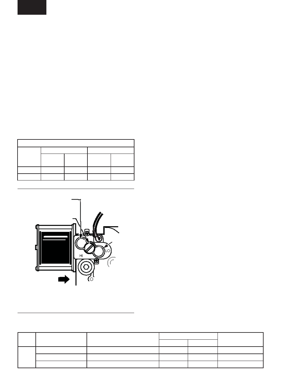
FIG. 3-2 – MANIFOLD GAS PRESSURE
ADJUSTMENT
HIGH FIRE PRESSURE
REGULATOR
LOW FIRE
PRESSURE
REGULATOR
TWO STAGE
PRESSURE
REGULATOR
REGULATOR VENT COVER
INLET
TABLE 3-2 – LOW FIRE / HIGH FIRE PRESSURES
TYPE OF
GAS
LINE PRESSURE
MANIFOLD PRESSURE
MINIMUM
MAXIMUM
LOW FIRE
+/- 0.3 “WC
HIGH FIRE
+/- 0.3 “WC
NATURAL
4.5 “WC
13.5 “WC
1.2 “WC
3.5 “WC
PROPANE
11.0 “WC
13.5 “WC
4.2 “WC
10.0”WC
LD11760a