Suction pressure transducer, Humidity sensors – York ECO2 YPAL 050 User Manual
Page 155
155
JOHNSON CONTROLS
FORM 100.50-NOM6 (1207)
8
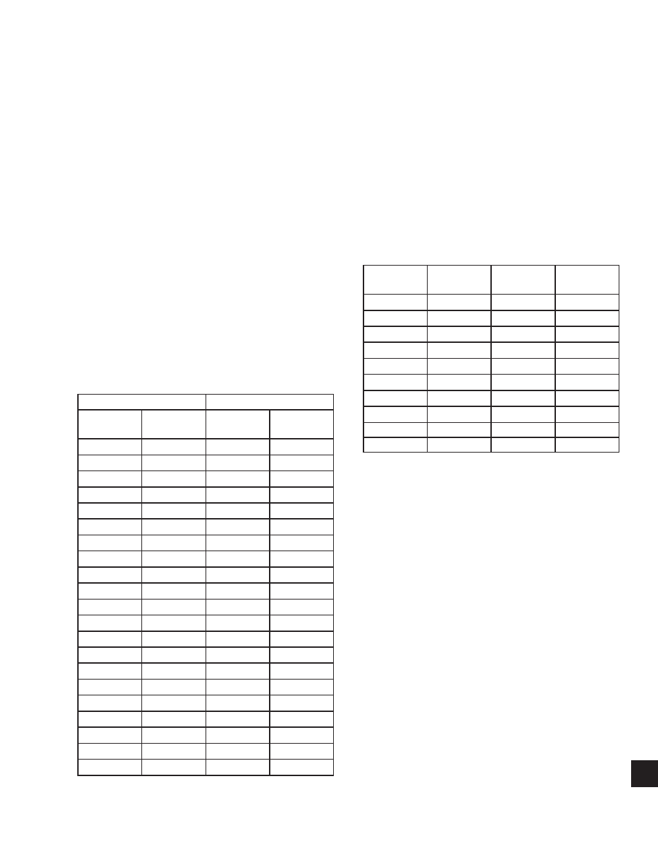
The Discharge Transducer has a range of 0 to 650
PSIG, with a linear output of 0 to 5 DC volts. Table
8-5 illustrates the DC volt output from the transducer
for a given discharge pressure.
Suction Pressure Transducer
The optional suction pressure transducer is located in
the common suction line of the tandem compressors for
each refrigerant circuit. The purpose of the transducer
is to sense and convert the suction pressure to a DC
voltage. The DC voltage is then sent to the Unit
Controller where it is displayed by the User Interface.
When this option is installed the Unit Controller will
also calculate and display the Evaporator Superheat
value for the system.
The Suction Transducer has a range of 0 to 400 PSIG,
with a linear output of 0 to 5 volts DC. Table 8-5
illustrates the DC volt output from the transducer for a
given suction pressure.
Humidity Sensors
The humidity sensor outputs a 0 to 5 volts DC in response
to the relative humidity sensed. An outdoor air humidity
sensor is used whenever the economizer is confi gured
for single or dual enthalpy. A return air humidity sensor
is used whenever the economizer is confi gured for dual
enthalpy. A humidity sensor is also used to monitor
the humidity in the space between the slab and raised
fl oor system used for FlexSys applications. Table 8-6
gives the relationship between the voltage output of the
humidity sensor and the % relative humidity.
SUCTION TRANSDUCER
DISCHARGE TRANSDUCER
PRESSURE
PSIG
VOLTAGE
VDC
PRESSURE
PSIG
VOLTAGE
VDC
0
0.5
0
0.5
25
0.75
32.5
0.7
50
1
65
0.9
75
1.25
97.5
1.1
100
1.5
130
1.3
125
1.75
162.5
1.5
150
2
195
1.7
175
2.25
227.5
1.9
200
2.5
260
2.1
225
2.75
292.5
2.3
250
3
325
2.5
275
3.25
357.5
2.7
300
3.5
390
2.9
325
3.75
422.5
3.1
350
4
455
3.3
375
4.25
487.5
3.5
400
4.5
520
3.7
552.5
3.9
585
4.1
617.5
4.3
650
4.5
TABLE 8-5 – PRESSURE TRANSDUCERS
% RELATIVE
HUMIDITY
% RELATIVE
HUMIDITY
5
0.25
55
2.75
10
0.50
60
3.00
15
0.75
65
3.25
20
1.00
70
3.50
25
1.25
75
3.75
30
1.50
80
4.00
35
1.75
85
4.25
40
2.00
90
4.50
45
2.25
95
4.75
50
2.50
100
5.00
TABLE 8-6 – HUMIDITY SENSOR OUTPUTS