Bottom supply / side return, General arrangement drawings (continued), Installation – York ECO2 YPAL 050 User Manual
Page 26: Airflow
26
JOHNSON CONTROLS
FORM 100.50-NOM6 (1207)
Installation
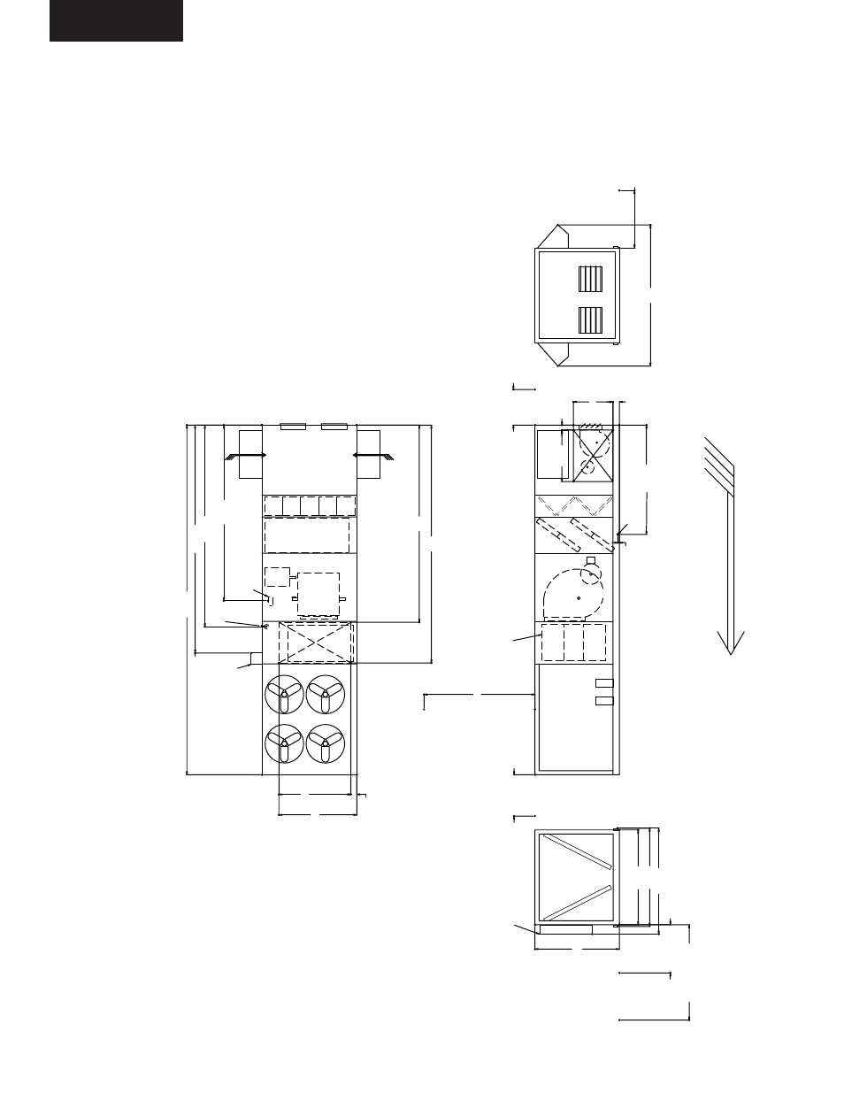
GENERAL ARRANGEMENT DRAWINGS (CONTINUED)
FIG. 2-4 – GENERAL ARRANGEMENT DRAWING (CONT.)
BOTTOM SUPPLY / SIDE RETURN
SECTION DESCRIPTIONS:
EE = Economizer
FE = Fan Exhaust
_F = Filter Segments
CC = Cooling Coils
FS = Supply Fan
DP
= Discharge Plenum
CO = Condenser Section
LD08370
6.28
38.37
49.94
4.79
GAS
BURNERS
GAS LINE CONNECTION 2-1/2" GAS OUTLET 1-1/2" MPT
CONN.
195.38
221.00
GAS HEA
T
FLUE
GAS HEA
T
EXHAUST
FLUE
FIELD INST
ALLED
102.62
T
O
P
VIEW
REAR VIEW
SIDE VIEW
(LEFT
SIDE)
FRONT
VIEW
1.50
78.00 CLEAR
FOR COIL
PULL
30.00
DOOR
SWING
CLEAR-
ANCE
BOTH
SIDES
95.25
92.00
82.00
84.00
CLEAR
91.00
CLEAR
FOR COIL
PULL
120.00 CLEAR
339.00
AIRFLOW
106.00
1-1/4" FPT
DRAIN
LEFT
SIDE ONL
Y
170.31
ELECTRICAL
SER
VICE
60.00 CLEAR
FOR AIR
INT
AKE
BOTH SIDES
136.82
OA
OA
69.83
75.58
5.74
230.62
191.19
NOTES:
1. 10’
clearance minimal over the top of the condensing unit.
2. Only one adjacent wall can exceed unit height.
3. 12’
clearance required to adjacent units.
4. 8’
service access recommended on one side.
5. Economizer and exhaust hoods, where applicable are folded inside unit for shipment.