Filters, Condensate drain, Condensate drain piping – York ECO2 YPAL 050 User Manual
Page 32: Condensate drain trap
32
JOHNSON CONTROLS
FORM 100.50-NOM6 (1207)
Installation
FILTERS
Two-inch “throwaway” filters are standard and factory
installed in a filter rack located prior to the evaporator
coil. Any optional pre-filters ordered with the unit will
be shipped inside the unit, but must be field installed.
The unit can also be ordered with an extended cabinet
and 95% efficient post-filters. These post-filters are
installed at the factory.
Pre-filters must always be installed ahead of the
evaporator coil. Post and pre-filters must be kept clean
and replaced with the same size and type as shipped with
the unit. Dirty filters will reduce the capacity of the unit
and may result in frosted coils and safety shutdowns.
Required filter sizes and quantities are shown in Table
2-6. The unit should never be operated for any length
of time without the proper filters installed in the unit.
CONDENSATE DRAIN
Condensate Drain Piping
The eco
2
cooling coils are located in the units so that
the supply air is drawn through them. This results in
the condensate being subjected to negative (-) static
pressure. Unless some means of pressure equalization is
provided in the condensate drains, the air rushing back
through the drainpipe will cause the condensate to build
up in the base rails. As the unit continues to operate, the
accumulated water will be carried with the air stream,
overfilling the base rails causing possible water leaks
into the supply duct and/or causing water damage in
the building. A trap must be installed to prevent this
condensate water build-up (see Figures 2-6 & 2-7).
Under high latent load conditions condensate may
form in the base and side rails of the unit. The unit is
designed to contain this moisture and prevent it from
leaking into the conditioned space. In order to dispose
of this condensate, two condensate drain connections
are located on the side rails on each side of the unit
and in the base rail on the return end of the unit. There
are five (5) condensate drains on the unit. Since these
connections are also under negative pressure, they must
be trapped using the same design criteria as the main
drain pan.
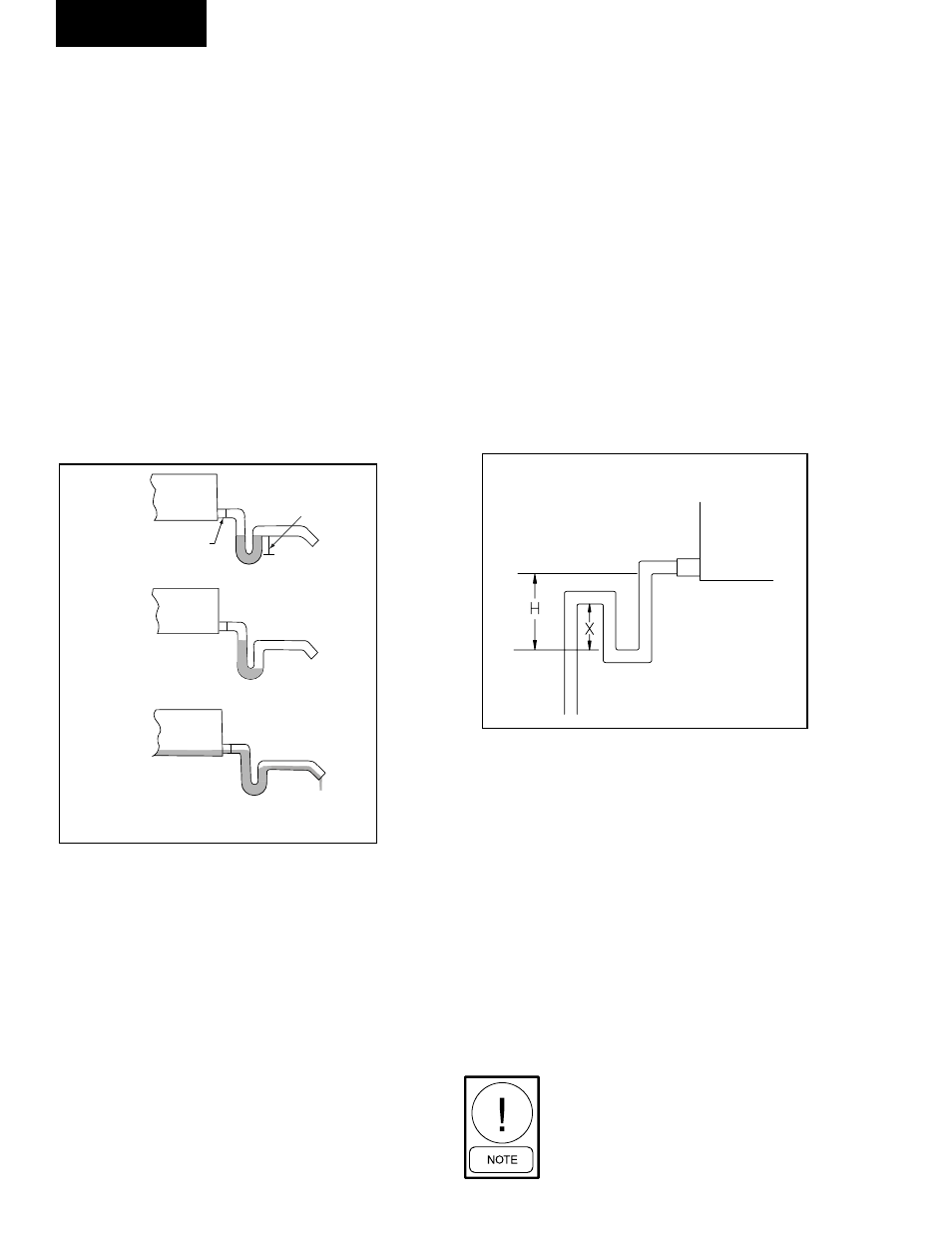
Condensate Drain Trap
For “Draw-through” applications install a trapped
condensate drain line at unit drain connection (see
Figure 2-7 according to all governing codes. “H”
dimension must be at least 1 inch greater than design
Total Static Pressure (TSP) of fan.
The trap and drain lines should be protected from
freezing. Plumbing must conform to local codes. Use
a sealing compound on male pipe threads. Install
condensate drain lines from the 1-1/4 inch NPT female
connections on the unit to an open drain.
The unit must be properly trapped and
charged with water before the units
are started.
FIG. 2-6
–
DRAIN TRAP SHOWING WATER
LOCATION DURING DRAW THROUGH
OPERATION STAGES
BASE
RAILS
BASE
RAILS
BASE
RAILS
DRAIN
NIPPLE
TRAP
NO.1 - FAN OFF
NO. 2 - TRAP CONDITION WHEN FAN STARTS
NO. 3 - FAN RUNNING AND CONDENSATE
COOLING COIL
DRAIN PAN
FIG. 2-7
–
TRAP DETAIL FOR DRAW THROUGH
APPLICATION
"H" must be at least
1 inch plus fan total
static pressure
"X" = 1/2 "H"
LD05370-1
LD13269