Combustion vent – York ECO2 YPAL 050 User Manual
Page 46
46
JOHNSON CONTROLS
FORM 100.50-NOM6 (1207)
Installation
6. The furnace and its individual manual shut-off
valve must be disconnected from the gas supply
piping system during any pressure testing of that
system at test pressures in excess of 0.5 PSIG.
Disconnect gas piping from unit when
leak testing at pressures greater than
0.5 PSIG. Pressures greater than 0.5
PSIG will cause gas valve damage
resulting in a hazardous condition.
If gas valve is subjected to pressure
greater than 0.5 PSIG, it must be
replaced.
7. A 1/8 inch N.P.T plugged tapping, accessible for
test gage connection, must be installed immedi-
ately upstream of the gas supply connection to the
furnace.
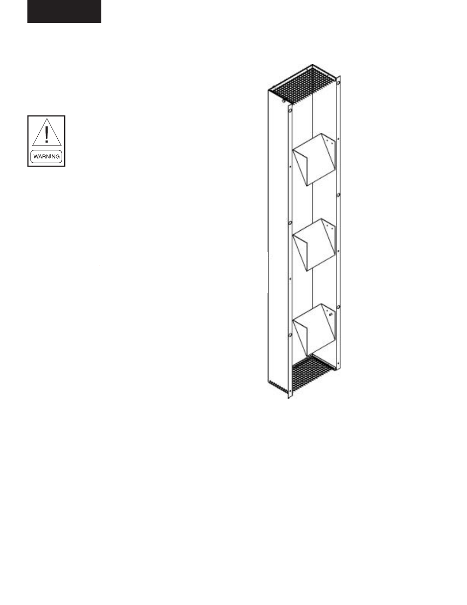
COMBUSTION VENT
The combustion vent assembly is shipped in the return
air section of the unit. The combustion vent assembly
must be mounted over the fl ue gas outlet fi xed panel
located to the right of the gas heat access door. Install
as follows:
1. Remove the combustion vent assembly from the
return compartment.
2. Remove the vertical row of six screws on either
side of the fl ue gas outlet fi xed panel.
3. Mount the combustion vent assembly over the fl ue
gas outlets and attach to the gas outlet fi xed panel
using the screws removed in step 2.
4. See Figure 2-14 for the proper orientation of the
combustion vent. The internal baffl e(s) must direct
the fl ue gases upward.
FIG. 2-14 – COMBUSTION VENT
LD11766