ZyXEL Communications ZyXEL ZyWALL 2WE User Manual
Page 365
ZyWALL 2 and ZyWALL 2WE
Hardware Specifications
33
Chart I-2 Console/Dial Backup Port Pin Assignments
CONSOLE Port RS – 232 (Female) DB-9F
DIAL BACKUP RS – 232 (Male) DB-9M
Pin 1 = NON
Pin 2 = DCE-TXD
Pin 3 = DCE –RXD
Pin 4 = DCE –DSR
Pin 5 = GND
Pin 6 = DCE –DTR
Pin 7 = DCE –CTS
Pin 8 = DCE –RTS
PIN 9 = NON
Pin 1 = NON
Pin 2 = DTE-RXD
Pin 3 = DTE-TXD
Pin 4 = DTE-DTR
Pin 5 = GND
Pin 6 = DTE-DSR
Pin 7 = DTE-RTS
Pin 8 = DTE-CTS
PIN 9 = NON.
The CON/AUX port also has these pin
assignments. The CON/AUX switch changes the
setting in the firmware only and does not change
the CON/AUX port’s pin assignments.
ZyWALLs with a CON/AUX port also have a 9-pin
adaptor for the console cable with these pin
assignments on the male end.
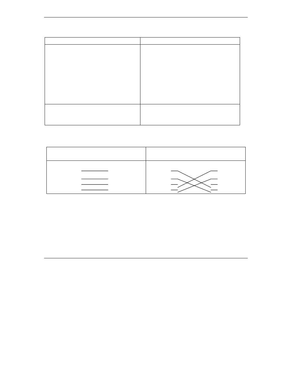
Chart I-3 Ethernet Cable Pin Assignments
WAN/LAN Ethernet Cable Pin Layout:
Straight-Through
Crossover
(Switch)
1 IRD +
(Adapter)
1 OTD +
(Switch)
1 IRD +
(Switch)
1 IRD +
2 IRD -
2 OTD -
2 IRD -
2 IRD -
3 OTD +
3 IRD +
3 OTD +
3 OTD +
6 OTD -
6 IRD -
6 OTD -
6 OTD -
- ISDN Terminal Adapter Omni.Net Lite (84 pages)
- ZYAIR G-360 V2 (2 pages)
- DMA-1000 Series (192 pages)
- PLA-450 (2 pages)
- EXT-108 (2 pages)
- P-2602HWLNI (496 pages)
- ZyXEL ZyWALL 2WG (730 pages)
- P841C (41 pages)
- Network Device P-2302 (359 pages)
- P-870M-I (2 pages)
- P-661HW Series (383 pages)
- Prestige 310 (161 pages)
- 802.11g Wireless Access Point ZyXEL G-560 (144 pages)
- P-2602HW (2 pages)
- Prestige 2602R Series (450 pages)
- 5 Series (835 pages)
- Prestige 623ME-T (253 pages)
- omni.net LCD series (53 pages)
- ZyXEL ZyAIR B-1000 (231 pages)
- P-2302HWUDL-P1 Series (368 pages)
- ZyXEL ZyWALL 5 (667 pages)
- Prestige 645R (180 pages)
- ZYWALL IDP 10 (42 pages)
- 802.11g Wireless Firewall Router P-320W (215 pages)
- PRESTIGE 660R-6XC (6 pages)
- 56K Plus II (88 pages)
- P-2802HW-i (2 pages)
- ZYAIR AG-200 (2 pages)
- POWERLINE PL-100 (33 pages)
- HomePlug AV DMA-1100P (198 pages)
- Access Router P-660R-T (9 pages)
- omni.net LCD+M (186 pages)
- G-162 (85 pages)
- PL-100 (33 pages)
- ZyXEL ZyAIR A-6000 (46 pages)
- ZyXEL ZyAIR AG-225H (14 pages)
- 2304R-P1 (124 pages)
- XTREMEMIMO M-302 (2 pages)
- nbg334s (2 pages)
- P-793H 601156 (1 page)
- Ethernet Extension Card EEC1020 (8 pages)
- P-871M (26 pages)
- Prestige 128L (114 pages)
- P-2812HNU-51c (2 pages)
- ZyWALL SSL 10 (64 pages)