4 functional block diagram, Diagram – Texas Instruments TMS320DM357 User Manual
Page 15
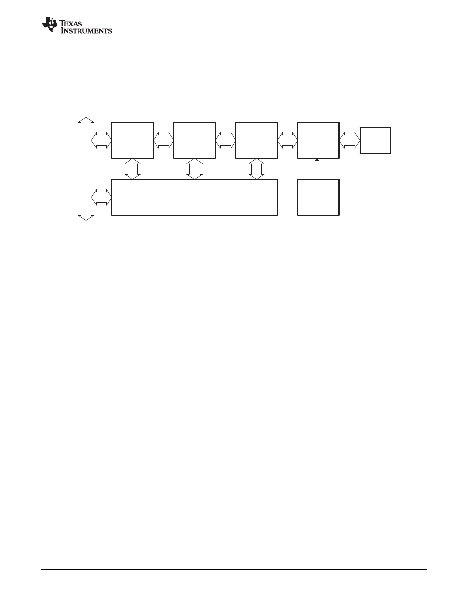
1.4
Functional Block Diagram
Internal
bus
CPPI
DMA
engine
FIFO
encode/
decode
Packet
USB
PHY
2.0
USB
24 MHz
oscillator
crystal
Registers, interrupts, endpoint control,
and packet scheduling
www.ti.com
Introduction
The USB functional block diagram is shown in
Figure 1. Functional Block Diagram
SPRUGH3 – November 2008
Universal Serial Bus (USB) Controller
15