Appendix d: led backplane connections, Schematic diagrams, Backplane supertrak controller card – Promise Technology Network Device EX8654 User Manual
Page 305
291
Appendix D: LED Backplane Connections
•
Schematic Diagrams (below)
•
•
Aggregate LED Display (page 293)
•
Schematic Diagrams
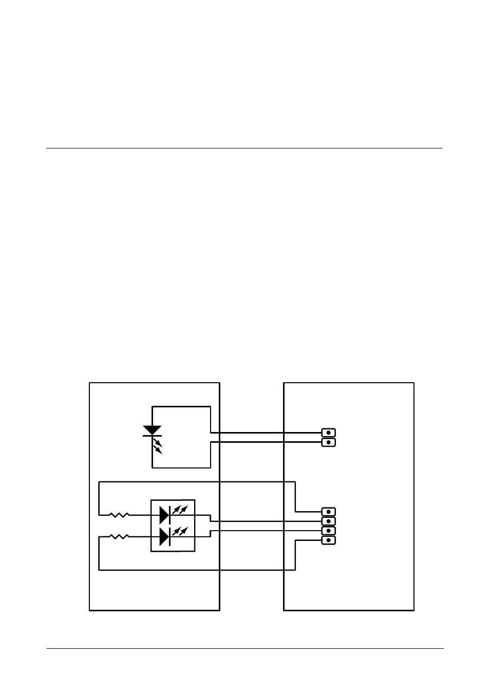
To set up LED configuration for your enclosure or PC, make your backplane
connections as shown below. You can make connections for:
•
Aggregate LEDs
•
Global LEDs in two colors
•
Direct connection – Individual fault and activity LEDs
For SuperTrak EX8654 and EX8658, note that only the interior SAS Ports
have individual LED pins.
For more information, see “Installing the SuperTrak Card” on page 9 and the user
manual for your PC or enclosure.
Figure 1. SuperTrak Aggregate and Global LED backplane connections
Aggregate
LEDs
Global
LEDs
Optional resistors for
tuning LED brightness.
Backplane
SuperTrak Controller Card
1
1
2
2
0
Ω
0
Ω
1
2
3
4
1
2
3
4
+
R
G
+
LED R+G
D-704578362
pin pitch 2.54 mm
for header
pin pitch 2.54 mm
for header
LED activity = Low