Configurations of terminals, Appendix, Input output – Sanyo PJLINK PLC-WM4500 User Manual
Page 85
5
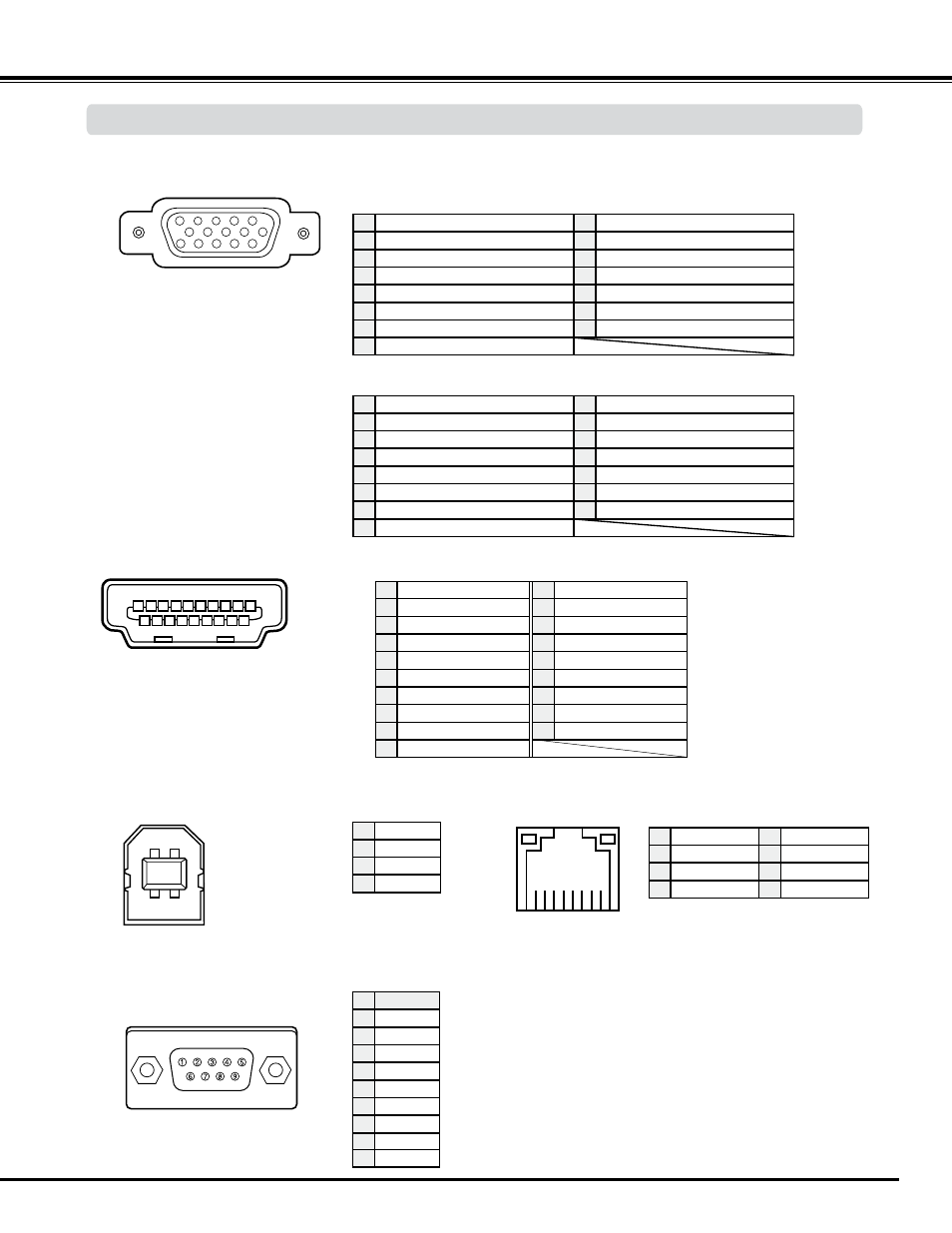
ANALOG/ MONITOR OUT (Mini D-sub 15 pin)
5
1
2
3
4
10
9
6
7
8
15
14
13
11
12
CONTROL PORT CONNECTOR (D-sub 9 pin)
-----
R X D
T X D
-----
SG
-----
RTS
CTS
Serial
1
4
5
6
7
Vcc
- Data
+ Data
Ground
1
4
USB CONNECTOR (Series B)
2
3
4
1
Appendix
-----
9
Red Input
Ground (Horiz.sync.)
Green Input
No Connect
Blue Input
Ground (Red)
Ground (Green)
Ground (Blue)
1
5
4
6
7
Horiz. sync. Input (Composite H/V sync.)
Ground (Vert.sync.)
DDC Data
Ground
Vert. sync. Input
DDC Clock
9
1
10
1
11
14
15
+5V Power
Red Output
Ground (Horiz.sync.)
Green Output
No Connect
Blue Output
Ground (Red)
Ground (Green)
Ground (Blue)
1
5
4
6
7
Horiz. sync. Output
Ground (Vert.sync.)
No Connect
No Connect
Vert. sync. Output
No Connect
9
1
10
1
11
14
15
No Connect
Input
Output
Configurations of Terminals
RX –
TX +
TX –
RX +
4
8 7 6 5 4 3 2 1
5
6
7
1
LAN TERMINAL
-----
-----
-----
-----
1 3 5 7 9 11 13 15 17 19
18
16
14
12
10
8
6
4
2
TMDS Data 2+ Input
Ground (TMDS Data 1)
Ground (TMDS Data 2)
TMDS Data 1+ Input
TMDS Data 2- Input
TMDS Data 1- Input
TMDS Data 0+ Input
Ground (TMDS Data 0)
1
5
2
4
3
6
7
8
Ground (TMDS Clock)
SCL
TMDS Clock- Input
-----
-----
SDA
Ground (DDC/CEC)
11
15
12
14
13
16
17
TMDS Data 0- Input
TMDS Clock+ Input
9
10
Plug insert detection
19
18 +5V Power
HDMI (19 Pin Type A)