6 analog input (adc) – Siemens MICROMASTER 440 User Manual
Page 38
6 Commissioning
Issue 10/06
MICROMASTER 440
38
Operating Instructions (Compact)
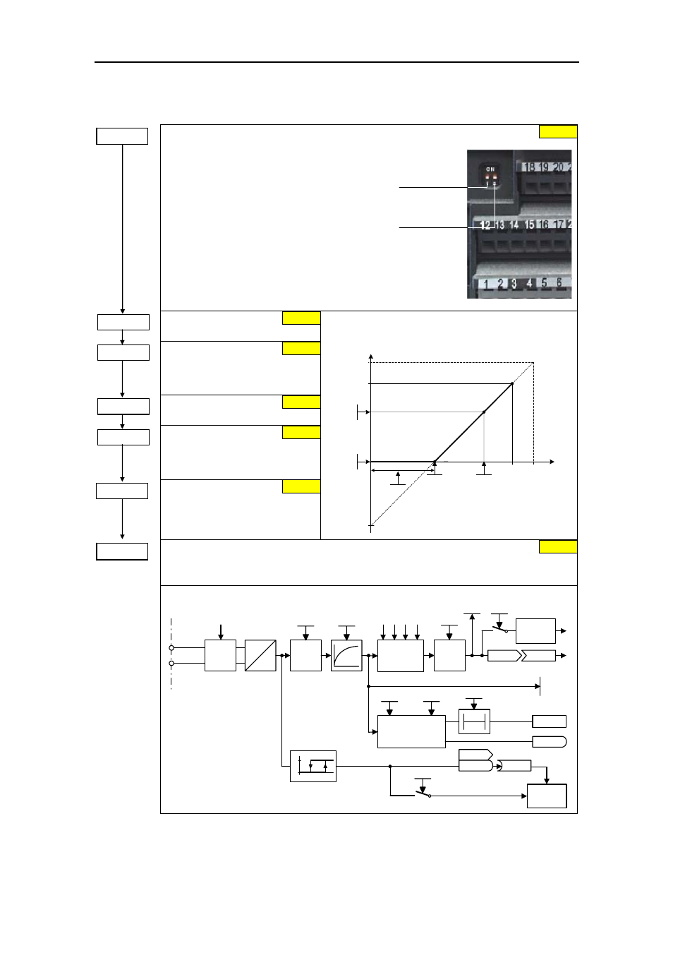
ADC1
ADC2
OFF = [V], 0 - 10 V
ON = [A], 0 - 20 mA
7
OFF = [V], 0 - 10 V
ON = [A], 0 - 20 mA
6.4.6
Analog input (ADC)
ADC type
Defines the analog input type and activates the monitoring
function of the analog input.
0 Unipolar voltage input (0 to +10 V)
1 Unipolar voltage input with monitoring
(0 to 10 V)
2 Unipolar current input (0 to 20 mA)
3 Unipolar current input with monitoring
(0 to 20 mA)
4 Bipolar voltage input (-10 to +10 V)
NOTE
For P0756 to P0760, the following applies:
Index 0 : Analog input 1 (ADC1), terminals 3, 4
Index 1 : Analog input 2 (ADC2), terminals 10, 11
P0757 =...
Value x1 of ADC scaling
P0758 =...
Value y1 of ADC scaling
This parameter represents the
value of x1 as a % of P2000
(reference frequency).
P0759 =...
Value x2 of ADC scaling
P0760 =...
Value y2 of ADC scaling
This parameter represents the
value of x2 as a % of P2000
(reference frequency).
Width of ADC deadband
Defines width of deadband on
analog input.
ASPmax
100 %
10 V
20 mA
V
mA
x
100%
%
P0760
P0758
P0759
P0761 > 0
0 < P0758 < P0760
||
0 > P0758 > P0760
ASPmin
P0757
P0761
P0757 = P0761
4000 h
Delay, ADC signal loss
Defines the delay time between the loss of the analog setpoint and fault message F0080
being displayed.
KL4
KL3
DIP switch
A
D
ADC
type
ADC
scaling
P
0757
P
0758
P
0759
P
0760
ADC
dead
zone
r0755
Pxxxx
r0752
P1000
ADC
−
ADC+
r0754
P0761
P0753
P0756
ADC
type
Setpoint
ADC channel
Wire
breakage
sensing
P0756
P0761
r0751
F0080
r0722
r0722.6
0
1
1.7 V
3.9 V
P0707
Pxxxx
Function
T
0
P0762
P0756 = ...
0
P0762 = ...
10 ms
0 V
0.0 %
10 V
100.0 %
0 V
P0761 =...