Twin pbt operation – Icom IC-7000 User Manual
Page 88
79
5
FUNCTIONS FOR RECEIVE
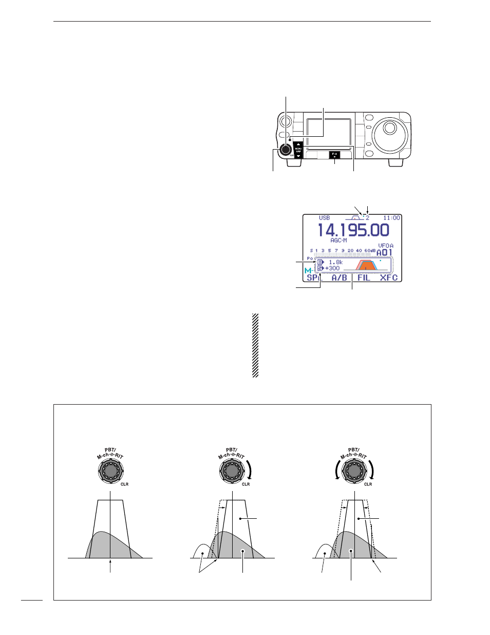
General PBT (Passband Tuning) function electronically
narrows the IF passband width by shifting the IF fre-
quency to slightly outside of the IF filter passband to
reject interference. This transceiver uses the DSP cir-
cuit for the PBT function. Moving both
[PBT
/M-ch/RIT
]
controls to the same position shifts the IF.
➥ Push [PBT/M-ch/RIT] momentarily to select the
twin PBT function, if the M-ch-RIT is selected.
•
[PBT/M-ch/RIT] indicator (Green) lights.
• The passband settings window shows the passband
width and shift frequency graphically. (The passband
settings window can be turned OFF in the display set
mode. p. 127)
➥ When M-1 is selected, push [F-3 FIL] for 1 sec. to
enter the filter set mode. Current passband width
and shift frequency is displayed in the filter set
mode.
➥ To set the [PBT
/M-ch/RIT
] controls to the center posi-
tions, push
[PBT
/M-ch/RIT
(
CLR
)] for 1 sec.
The limit of the variable range depends on the pass-
band width and mode. The edge of the variable range
is half of the passband width, and PBT is adjustable in
100 (AM) or 25 Hz steps (other modes).
•
[PBT] controls should normally be set to the center posi-
tions (PBT setting is cleared) when there is no interfer-
ence.
• When PBT is used, the audio tone may be changed.
• Not available for FM or WFM modes.
• While rotating
[PBT], noise may occur. This comes from
the DSP unit and does not indicate an equipment mal-
function.
Passband
width
Selected IF filter
Shift
frequency
Popup indicator appears
Dot indicator appears
when PBT is activate
[MENU/GRP]
[F-3]
[PBT/M-ch/RIT] indicator
[PBT
/M-ch/RIT
(CLR)] switch/[PBT] (inner) control
[PBT] (outer) control
PBT OPERATION EXAMPLE
IF center frequency
Interference Desired signal
Passband
Both controls at
center position
Cutting a lower
passband
Cutting both higher and
lower passbands
Interference
Interference
Desired signal
Passband
■ Twin PBT operation