Zone 2 —continued, Using the remote control in zone 2, Using the 12v trigger – Integra DTR-8.4 User Manual
Page 85: Using a multiroom kit with zone 2, Using a multiroom kit with a cabinet, Using a multiroom kit with other components
85
Zone 2
—Continued
Using the 12V Trigger
While Zone 2 is active on the DTR-8.4, the ZONE 2 12V
TRIGGER OUT outputs 12 volts (100 milliamperes
max). By connecting this to the 12-volt trigger input on,
say, a power amp in Zone 2, the power amp will turn on
and off automatically when Zone 2 is turned on and off
on the DTR-8.4.
To use the remote controller to control the DTR-8.4 from
Zone 2, you’ll need one of the following commercially
available multiroom remote control kits:
• Onkyo Multiroom Kit (IR remote controller extension
system)
• Multiroom AV distribution and control systems such
as those made by Niles and Xantech.
These kits can also be used when the DTR-8.4 is not in
line of sight of the remote controller, for example, when
it’s installed inside a cabinet.
You can set the transmission signal format to RF for use
with the optional RF Receiver (see page 98).
Using a Multiroom Kit with Zone 2
In the following diagram, an IR receiver picks up the
infrared signals from the remote controller in Zone 2 and
feeds them to the DTR-8.4 in the main room via the con-
necting block.
• On the Remote Setup menu, set the Position setting to
“Zone 2” (see page 48).
Connect the miniplug cable from the connecting block to
the DTR-8.4’s IR IN socket as shown below.
Using a Multiroom Kit with a Cabinet
In the following diagram, an IR receiver picks up the
infrared signals from the remote controller and feeds
them to the DTR-8.4 in the cabinet via the connecting
block.
• On the Remote Setup menu, set the Position setting to
“Main” (see page 48).
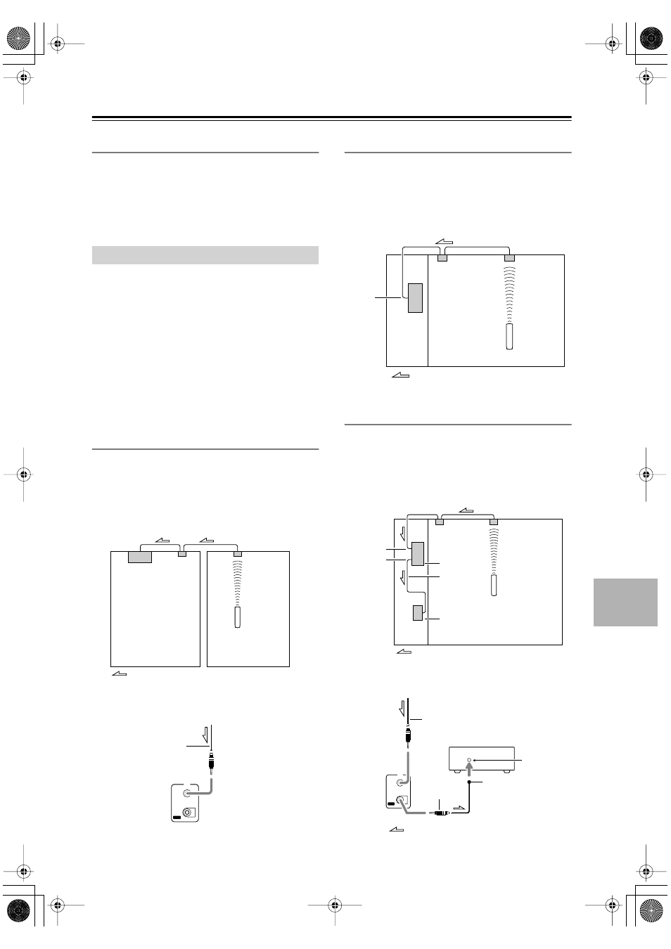
Using a Multiroom Kit with Other
Components
In the following diagram, an IR emitter is connected to
the DTR-8.4’s IR OUT socket and placed in front of the
other component’s remote control sensor. Only infrared
signals received at the IR IN socket are fed to the other
component. Signals picked up by the DTR-8.4’s remote
control sensor are not passed on.
Connect the IR emitter to the DTR-8.4’s IR OUT socket
as shown below.
Using the Remote Control in Zone 2
DTR-8.4
Connecting
block
Remote controller
IR Receiver
Main room
Zone 2
Signal flow
DTR-8.4
I R
IN
OUT
from the connecting block
Miniplug cable
IR IN
DTR-8.4
Connecting
block
Remote controller
IR Receiver
Inside
cabinet
Signal flow
DTR-8.4
IR IN
IR OUT
Connecting
block
IR Receiver
Remote controller
Signal flow
IR Emitter
Other component
DTR-8.4
I R
IN
OUT
Remote control
sensor
Other component
Emitter
IR Emitter
Signal flow
Miniplug
Miniplug cable