Connecting the dtr-8.4 —continued, Connecting antenna, Connecting the indoor fm antenna – Integra DTR-8.4 User Manual
Page 24: Connecting the am loop antenna
24
Connecting the DTR-8.4
—Continued
This chapter explains how to connect the supplied indoor
FM antenna and AM loop antenna, and how to connect
commercially available outdoor FM and AM antennas.
The DTR-8.4 won’t pick up any radio signals without
any antenna connected, so you must connect the antenna
to use the tuner.
Connecting the Indoor FM Antenna
The supplied indoor FM antenna is for indoor use only.
If you cannot achieve good reception with the supplied
indoor FM antenna, try a commercially available out-
door FM antenna instead (see page 25).
Connecting the AM Loop Antenna
The supplied indoor AM loop antenna is for indoor use
only.
If you cannot achieve good reception with the supplied
indoor AM loop antenna, try using it with a commer-
cially available outdoor AM antenna (see page 25).
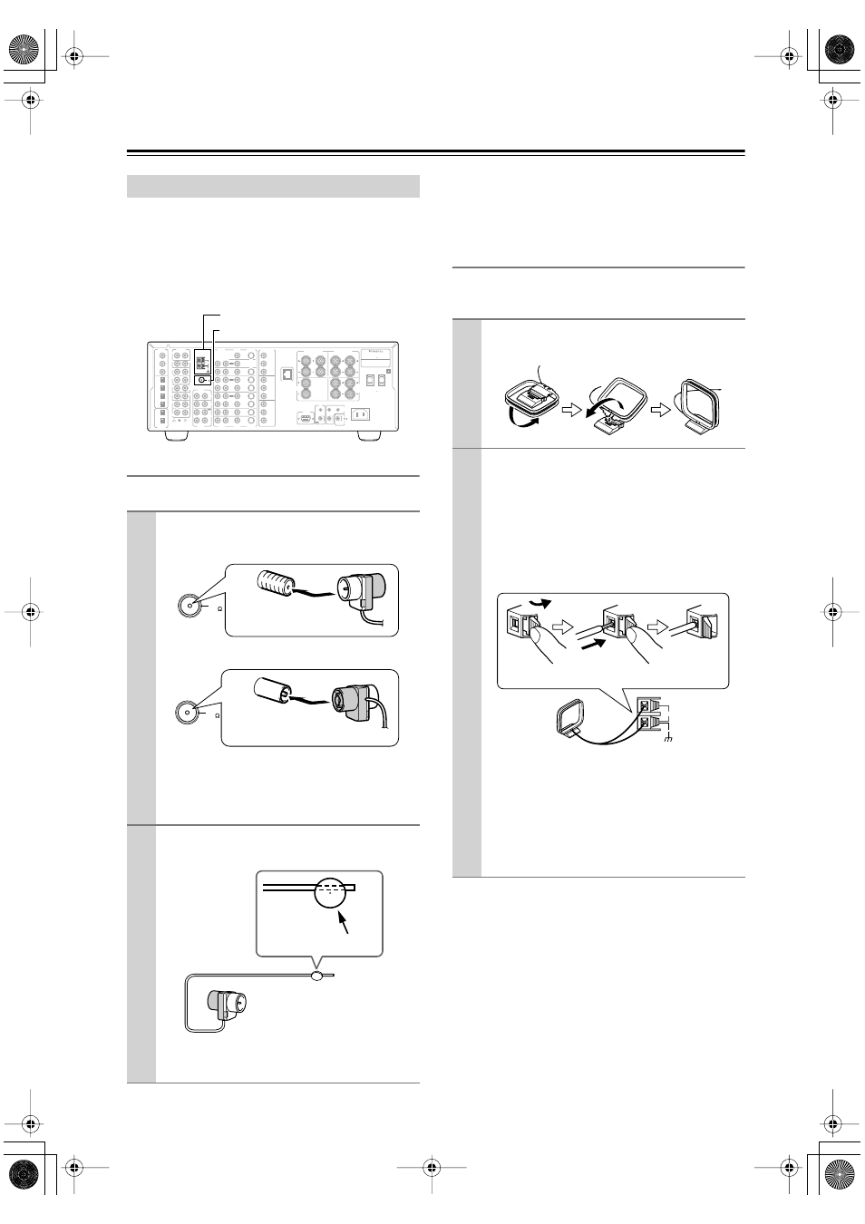
Connecting Antenna
1
Attach the FM antenna, as shown.
■
U.S.A. and Canadian Models
■
Australian Model
Once your DTR-8.4 is ready for use, you’ll need
to tune into an FM radio station and adjust the
position of the FM antenna to achieve the best
possible reception.
2
Use thumbtacks or something similar to
fix the FM antenna into position.
Caution:
Be careful that you don’t injure yourself
when using thumbtacks.
FM
75
OUT
OUT
OUT
OUT
L
PHONO
PRE OUT
FRONT
SUB
SURR
R
L
AUDIO
R
L
CD
TAPE
R
L
AUDIO
VIDEO
S VIDEO
MONITOR
OUT
R
L
IN
IN
IN
IN
IN
IN
IN
ZONE 2
DVD
VIDEO 1
VIDEO 2
VIDEO 3
VIDEO 4
AUDIO
AUDIO
VIDEO
S VIDEO
GND
SURR
BACK/
ZONE 2
R
L
IN
AC INLET
R
CENTER
ETHERNET
(Net -Tune)
R
L
MULTI CH
INPUT
FRONT
SUB
SURR
SURR
BACK
CENTER
R
L
AM
ANTENNA
COMPONENT
VIDEO
Y
PB
PR
OUTPUT
INPUT 1
Y
PB
PR
INPUT 2
Y
PB
PR
SURR
BACK/
ZONE 2
SPEAKERS
FRONT SPEAKERS
L
R
L
R
SURR SPEAKERS
CENTER
SPEAKER
R
L
AC OUTLETS
AV RECEIVER
MODEL NO.
DTR-8.4
RATING: AC 120 V 60 Hz 9.0 A
AC 120 V 60 Hz
SWITCHED
TOTAL 120W 1A MAX.
I R
IN
ZONE 2
REMOTE
CONTROL
A
B
RS232
OUT
12 V
TRIGGER OUT
DIGITAL
IN
DIGITAL
OUT
OPT
OPT
2
1
2
3
4
1
2
1
3
COAX
AM antenna push terminals
FM antenna connector
FM
75
Insert the plug fully
into the socket.
FM
75
Insert the plug fully
into the socket.
Thumbtacks, etc.
1
Assemble the AM loop antenna, inserting
the tabs into the base, as shown.
2
Connect both wires of the AM loop
antenna to the AM push terminals, as
shown.
(The antenna’s wires are not polarity sensitive, so
they can be connected either way around).
Make sure that the wires are attached securely and
that the push terminals are gripping the bare
wires, not the insulation.
Once your DTR-8.4 is ready for use, you’ll need
to tune into an AM radio station and adjust the
position of the AM antenna to achieve the best
possible reception.
Keep the antenna as far away as possible from
your DTR-8.4, TV, speaker cables, and power
cords.
AM
Push Insert
wire
Release