Connecting the dtr-8.4 —continued, Connecting your tv or projector, Video connection formats – Integra DTR-8.4 User Manual
Page 27: Tv, projector, etc
27
Connecting the DTR-8.4
—Continued
The DTR-8.4 offers several connection formats for com-
patibility with a wide range of AV equipment. The for-
mat you choose will depend on the formats supported by
your AV components. Use the following section as a
guide.
Video Connection Formats
Video equipment can be connected to the DTR-8.4 using
the following video connection formats: composite
video, S-Video, or component video, the latter offering
the best picture quality.
The following diagram shows that composite video input
signals are output by composite video and S-Video out-
puts, and that S-Video input signals are output by
S-Video and composite video outputs.
If you connect a video source to a component video
input, you’ll need to connect your TV or projector to the
component video output. Normally, component video
input #1 or #2 feeds the component video output. How-
ever, you can configure the DTR-8.4 to output composite
video and S-Video input signals as component video (see
“Component Video Setup” on page 47).
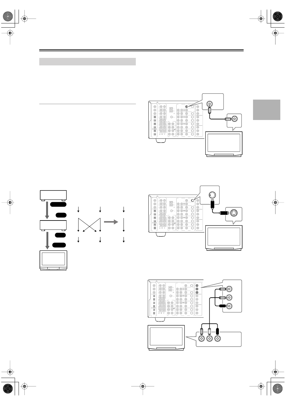
Depending on the type of video input on your TV, choose
one of the following connection methods.
■
Using Composite Video
Use a composite video cable to connect the DTR-8.4’s
VIDEO MONITOR OUT to a composite video input on
your TV, as shown.
■
Using S-Video
Use an S-Video cable to connect the DTR-8.4’s
S VIDEO MONITOR OUT to an S-Video input on your
TV, as shown.
■
Using Component Video
Use a component video cable to connect the DTR-8.4’s
COMPONENT VIDEO OUTPUT to a component video
input on your TV, as shown.
Connecting Your TV or Projector
DTR-8.4
DVD player,
etc.
TV,
projector,
etc.
Composite
S-Video
Component
Output
IN
OUT
Input
Composite
S-Video
Component
Composite
S-Video
Component
Composite
S-Video
Component
page 47
FM
75
OUT
OUT
OUT
OUT
L
PHONO
DIGITAL
IN
PRE OUT
DIGITAL
OUT
OPT
OPT
2
1
2
3
4
1
2
FRONT
SUB
SURR
R
L
AUDIO
R
L
CD
TAPE
R
L
AUDIO
VIDEO
S VIDEO
MONITOR
OUT
R
L
IN
IN
IN
IN
IN
IN
IN
ZONE 2
DVD
VIDEO 1
VIDEO 2
VIDEO 3
VIDEO 4
AUDIO
AUDIO
VIDEO
S VIDEO
1
3
GND
SURR
BACK/
ZONE 2
R
L
IN
COAX
R
CENTER
R
L
MULTI CH
INPUT
FRONT
SUB
SURR
SURR
BACK
CENTER
R
L
AM
ANTENNA
COMPONENT
VIDEO
Y
P
B
P
R
OUTPUT
INPUT 1
Y
P
B
P
R
INPUT 2
Y
P
B
P
R
VIDEO IN
VIDEO
MONITOR
OUT
TV, projector,
etc.
FM
75
OUT
OUT
OUT
OUT
L
PHONO
DIGITAL
IN
PRE OUT
DIGITAL
OUT
OPT
OPT
2
1
2
3
4
1
2
FRONT
SUB
SURR
R
L
AUDIO
R
L
CD
TAPE
R
L
AUDIO
VIDEO
S VIDEO
MONITOR
OUT
R
L
IN
IN
IN
IN
IN
IN
IN
ZONE 2
DVD
VIDEO 1
VIDEO 2
VIDEO 3
VIDEO 4
AUDIO
AUDIO
VIDEO
S VIDEO
1
3
GND
SURR
BACK/
ZONE 2
R
L
IN
COAX
R
CENTER
R
L
MULTI CH
INPUT
FRONT
SUB
SURR
SURR
BACK
CENTER
R
L
AM
ANTENNA
COMPONENT
VIDEO
Y
P
B
P
R
OUTPUT
INPUT 1
Y
P
B
P
R
INPUT 2
Y
P
B
P
R
S VIDEO IN
S VIDEO
MONITOR
OUT
TV, projector,
etc.
FM
75
OUT
OUT
OUT
OUT
L
PHONO
DIGITAL
IN
PRE OUT
DIGITAL
OUT
OPT
OPT
2
1
2
3
4
1
2
FRONT
SUB
SURR
R
L
AUDIO
R
L
CD
TAPE
R
L
AUDIO
VIDEO
S VIDEO
MONITOR
OUT
R
L
IN
IN
IN
IN
IN
IN
IN
ZONE 2
DVD
VIDEO 1
VIDEO 2
VIDEO 3
VIDEO 4
AUDIO
AUDIO
VIDEO
S VIDEO
1
3
GND
SURR
BACK/
ZONE 2
R
L
IN
COAX
R
CENTER
R
L
MULTI CH
INPUT
FRONT
SUB
SURR
SURR
BACK
CENTER
R
L
AM
ANTENNA
COMPONENT
VIDEO
Y
P
B
P
R
OUTPUT
INPUT 1
Y
P
B
P
R
INPUT 2
Y
P
B
P
R
COMPONENT
VIDEO IN
COMPONENT
VIDEO
Y
P
B
P
R
OUTPUT
Y
P
B
P
R
TV, projector,
etc.