BendixKing KMD 250 User Manual
Page 80
1-61
Rev 2 Apr/2004
KMD 250 Pilot's Guide
Section 1
Basic Operation
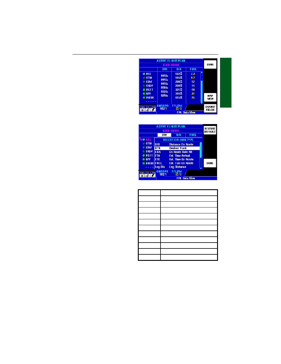
FUEL FLOW
If the KMD 250 is installed in
conjunction with a fuel flow
monitor, the actual fuel flow
and estimated fuel usage cal-
culations will be displayed in
white as in Figure 1-107. This
will allow the KMD 250 to cal-
culate the fuel flow for each leg
of the flight plan based on cur-
rent ground speed. If no fuel
flow monitor is used, the value
may be entered manually by
using the Joystick to select the
FFLOW field. Use the Rotary
Knob to enter the desired
value. User entered values,
and calculations based on user
entered data are displayed in
yellow as seen in Figure 1-108.
NOTE: Fuel flow values can
only be entered manually on
the ACTIVE FLIGHT PLAN
Page if no fuel flow monitor is
installed.
CHANGING THE DATA
COLUMNS
The three data columns can be
changed to reflect various types
of information for each leg. To
change the columns perform the
following steps.
1.
Press the CHANGE
FIELDS Softkey to display
Figure 1-109.
2.
Move the Joystick horizon-
tally to select the desired data column (in this case the first column).
3.
Turn the Rotary Knob to select one of the available options from the
list. Each field can be customized to display any of the following:
4.
Press the DONE Softkey when finished and the columns will now
display the selected data options.
Pressing the RESTORE DEFAULT Softkey to change the columns back
to the factory settings.
Flight Plan Operation
Figure 1-108
Figure 1-109
DIS
Distance En Route
DTK
Desired Track
ESA
En Route Safe Altitude
ETA
Estimated Time of Arrival
ETE
Estimated Time En Route
FUEL
Estimated Fuel En Route
Leg Dis
Leg Distance
Leg Fuel
Estimated Leg Fuel
Leg MSA Leg Minimum Safe Altitude
Leg Time Estimated Leg Time
Sunrise
Sunrise Time
Sunset
Sunset Time