Pulse mode wiring, differential inputs – Emerson 400518-01 User Manual
Page 46
34
Safety Information
Product Overview
Installation
Diagnostics
Options and
Accessories
Specification
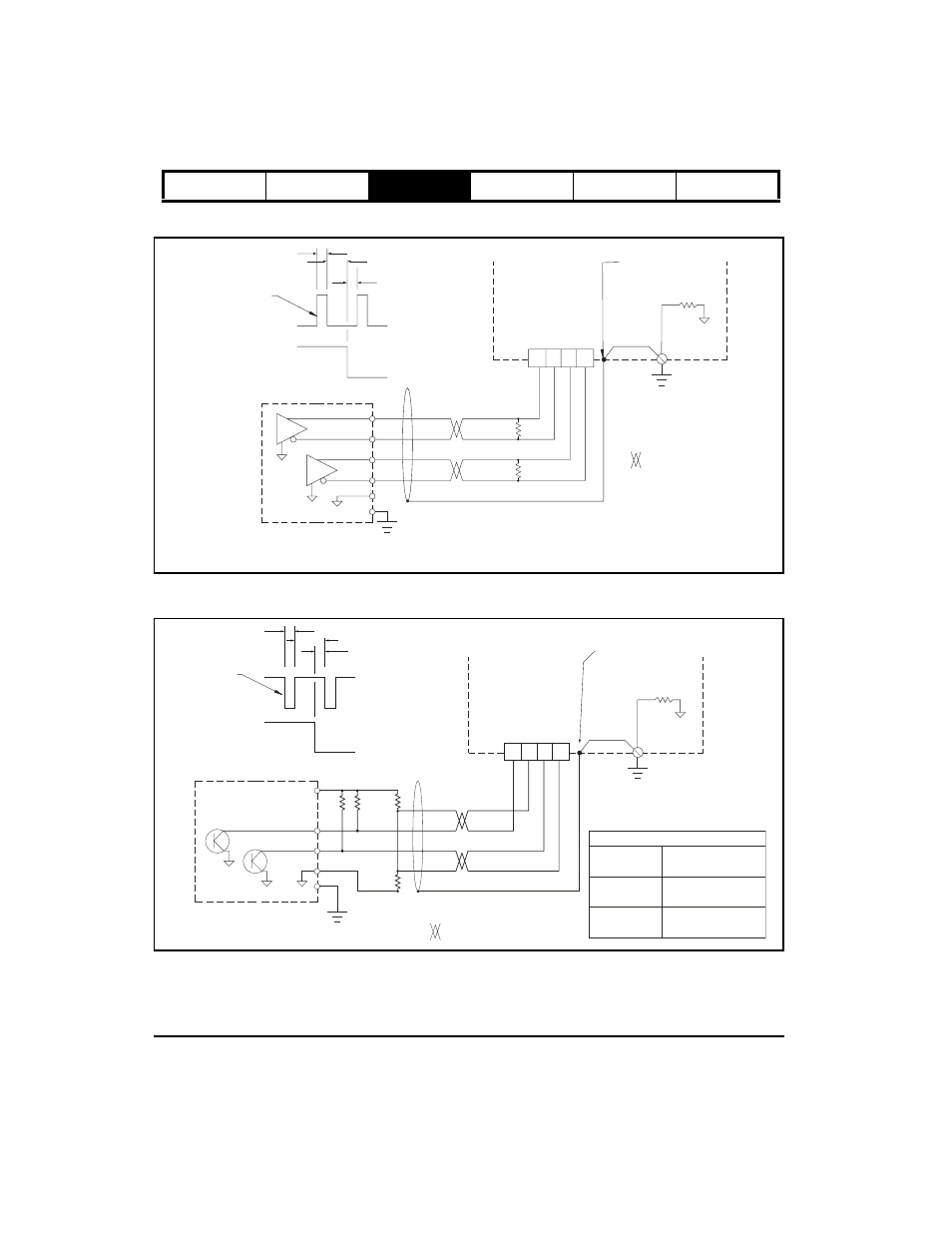
Pulse Mode Wiring, Differential Inputs
Figure 37:
Pulse Mode, Differential Output to Differential Input
Figure 38:
Pulse Mode, Single Ended Output to Differential Input
= Twisted Pair
If the external controller does not have an internal terminating
resistor R1, and R2 must be mounted within 3 ft [1 m] of the drive.
A 120 ohm resistor is recommended for high frequency
(over 250 kHz) feedback signals or cable lengths longer
than 25 feet.
Note:
10 Ohm
Shield connected
to connector shell
Single Point
Panel Ground
Single Point
PE Ground
PE
Drive
250 ns Minimum
500 ns Minimum
500 ns Minimum
(A) Pulse
(B) Direction
Motion occurs
on rising edge
CW
CCW
RS-422 Type
Differential Drives
1 2 3 5
A A/ B B/
R1
R2
Sync Input Connector
(J10)
(B) Direction
CW
CCW
(A/) Pulse
500 ns Minimum
250 ns Minimum
500 ns Minimum
Motion occurs
on falling edge
Resistor Values
= Twisted Pair
10 Ohm
Shield connected
to connector shell
PE
Drive
1 2 3 5
Sync Input Connector
(J10)
A A/ B B/
Single Point
Panel Ground
Single Point
PE Ground
1K Ohm Maximum
240 Ohm Minimum
1/2 R3
120 Ohm Minimum
1K Ohm Maximum
240 Ohm Minimum
R1, R2
R3
R4
Direction
Pulse
+5 Out
R1
R2
R3
R4