Motor brake wiring, Installation 25 – Emerson 400518-01 User Manual
Page 37
Installation
25
Safety Information
Product Overview
Installation
Diagnostics
Options and
Accessories
Specification
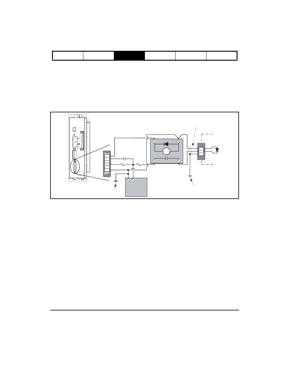
Motor Brake Wiring
The NT and MG motors equipped with brakes have a three-pin MS style connector. The brake power cable (model
CBMS-XXX) has an MS style connector on the motor end and three wire leads on the drive end (see the following
wiring diagrams). The XV 40-80 mm motors with brakes have a two-position connector. The brake power cable
(model XTBMS-XXX) has a two position connector on the motor end and three wire leads on the drive end. The XV
130 mm motors equipped with brakes have two MS style connectors; one is the encoder feedback and the other has
the motor power and brake connections. The motor power/brake cable (model XCMDBS-XXX) has an MS style
connector on the motor end and six wire leads on the drive end.
You must provide a DC power supply rated at +24 Vdc with a 2 A minimum current capacity for the brake. If you use
this voltage source to power other accessories such as I/O or more than one brake, size the power supply for total
load.
Figure 23: Epsilon EP to NT or MG Motor Brake Wiring Diagram
EP204-I00-0000
9606XX-XX A1
SN 0610E014
motor
logic
+
_
L1
L2
PE
R
S
T
digital i/o (J3)
19
10
8
Output #3
Drive Enable
I/O Common
I/O Supply
J3
-
+
K1
Internal
to Motor
Red +
Black -
Connected to
grounded
mounting panel.
Single point
PE ground
11
A2
14
A1
2 Amp
Fuse
Customer
supplied drive
enable contact
Relay:
Model# BRM-1
24 VDC
NT or MG
Motor
1 Amp
Fuse
CBMS-xxx Cable
20
A
C
B