Motor feedback wiring (j6), Motor overtemp wiring, Nt/mg motor – Emerson 400518-01 User Manual
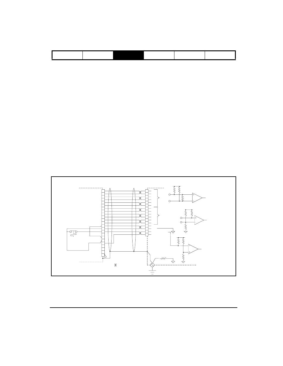
Page 35: Installation 23, Figure 20: motor encoder feedback connector pinout
Installation
23
Safety Information
Product Overview
Installation
Diagnostics
Options and
Accessories
Specification
to the logic supply are PELV, the wiring need not be isolated from direct contact within a zone of equipotential
bonding, normally an enclosure or set of enclosures bonded together. Otherwise, logic wiring and circuits must be
isolated from direct contact by basic insulation for 300 V system voltage.
In all applications, do not interconnect extra low voltage power supplies so that voltages add.
Motor Feedback Wiring (J6)
Encoder feedback connections are made with the 15-pin high density “D” connector (J6) on the drive. Maximum
feedback cable length is 200 ft [60 m].
Connection of Encoder Quadrature and Marker Signals
For A, A/, B, B/ and Z, Z/ pairs, Control Techniques cables use low capacitance (~10 pf/ft) wire to get a high
characteristic impedance and low loss. The differential input circuit accepts RS-485 level signals, but if the differential
voltage is less than ±400 mV, an encoder fault is generated.
Connection of Encoder Commutation Signals to the Drive
The drive is capable of receiving U, V, and W commutation signals from either a differential or single ended source.
Figures 20 through 22 show a simplified circuit for the U, U/, V, V/, W, and W/ inputs on the drive. For single-ended
encoder outputs, leave U/, V/, and W/ unconnected at the drive. No PowerTools configuration is required. U, V, and
W have a 1K pull-up to 5V. Logic threshold is about 2.5 V with 0.1 V hysteresis.
Motor Overtemp Wiring
The motor overtemp circuit is compatible with PTC thermistor sensor with 1K resistance at the over temperature trip
point. The circuit provides 5V open circuit and 0.5 mA closed contacts to an overload switch. For motors without over
temperature protection sensors, pins 14 and 15 of J6 must be shorted together to prevent an overtemp fault in the
drive.
NT/MG Motor
Figure 20:
Motor Encoder Feedback Connector Pinout
NT or MG Motor
Blue
Orange
Green
Brown
Black
Yellow
White/Brown
Brown/White
White/Gray
Gray/White
Red/Orange
Orange/Red
*Red/Blue
Blue/Red
Red/Green
Green/Red
8
12
14
1
2
4
3
5
6
7
9
10
11
13
15
R
H
T
J
B
C
P
N
M
U
E
F
S
G
K
A
L
D
V
W
U/
W/
A
A/
B/
B
Z
Z/
U
V
V/
W
+ 5 Vdc
+ 5 Vdc
Shield
X
Y
Z
Connector Shell
Internal
Motor
Thermal
Switch
GND
Motor
Overtemp
Overtemp GND
= Twisted Pair
Single Point
Ground
Epsilon EP
Drive
U/
W/
A
A/
B/
B
Z
Z/
U
V
V/
W
+5 Vdc
GND
Motor Overtemp
10K
+5 V
10K
1.0K
10 Ohm
PE
Differential
Receiver
2K
U/
+5 V
2K
U
1K
2K
A/
+5 V
2K
220 Ohm
Differential
Receiver
A
Motor Feedback Cable
Model # EFCS-XXX