Sync input connector (j10), Installation 31 – Emerson 400518-01 User Manual
Page 43
Installation
31
Safety Information
Product Overview
Installation
Diagnostics
Options and
Accessories
Specification
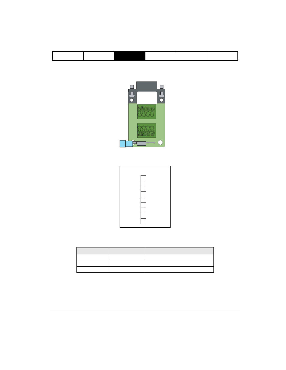
Sync Input Connector (J10)
Sync Input signals are connected to the drive using the 9-pin Sync Input connector.
If interfacing the drive using field wiring, the optional standard terminal interface board (STI-SNCI) may be used.
Figure 31:
STI-SNCI Interface Board
Figure 32:Analog Input Connector (J10) Functions
The Sync Input power meets EMC emissions and immunity for cables longer than 3 meters [10 ft], when using a
shielded cable. When a remote encoder is user, cable length may be limited by encoder supply voltage drop, and
should not exceed 200 ft [60 m].
Function
Pin Number
Electrical Characteristics
Encoder In
1, 2, 3, 5, 6, 7
Differential line driver input (RS 422)
5 Vdc
4
+5 Vdc supply voltage
Ground
8
Logic Common
1 2 3 4
5 6 7 8
Encoder B
+ 5 Vdc
7
8
9
5
6
4
3
1
2
Encoder A
Encoder Z
Encoder A/
Encoder Z/
NC
Logic Common
Encoder B/
Function
J10 Connector
Pin#