Emerson Liebert Challenger ITR User Manual
Liebert, Challenger
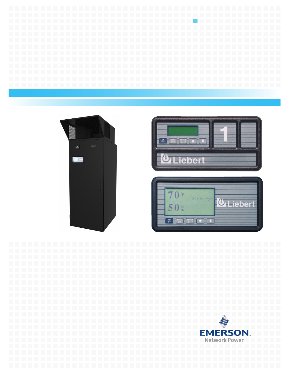
Table of contents
Document Outline
- Product Nomenclature
- 1.0 Dedicated, Precise Environmental Control
- 2.0 Precision Environmental Control for Industrial, Telecommunications, Medical and Data Processing Equipment
- 3.0 Local Monitoring Systems
- 4.0 Standard Features-All Systems
- 5.0 Chilled Water System-Standard and Optional Features
- 6.0 Refrigeration Systems
- 7.0 Air-Cooled System-Standard and Optional Features
- 8.0 Water/Glycol-Cooled Systems-Standard and Optional Features
- 9.0 GLYCOOL Systems-Standard and Optional Features
- 10.0 Optional Equipment-All Systems
- 11.0 Comprehensive Monitoring Systems-Optional
- 12.0 Comprehensive Monitoring Solutions-Optional
- 13.0 System Data
- Table 2 Liebert Challenger ITR air-cooled data-60 Hz
- Table 3 Liebert Challenger ITR air-cooled data-60 Hz (continued)
- Table 4 Liebert Challenger ITR air-cooled data-50 Hz
- Table 5 Liebert Challenger ITR air-cooled data-50Hz (continued)
- Table 6 Liebert Challenger ITR water cooled data, 60 Hz
- Table 7 Liebert Challenger ITR water cooled data, 60 Hz (continued)
- Table 8 Liebert Challenger ITR water cooled data, 50 Hz
- Table 9 Liebert Challenger ITR water cooled data, 50 Hz (continued)
- Table 10 Liebert Challenger ITR glycol cooled data, 60 Hz
- Table 11 Liebert Challenger ITR glycol cooled data, 60 Hz (continued)
- Table 12 Liebert Challenger ITR glycol cooled data, 50 Hz
- Table 13 Liebert Challenger ITR glycol cooled data, 50 Hz (continued)
- Table 14 Liebert Challenger ITR chilled water data, 60 Hz
- Table 15 Liebert Challenger ITR chilled water data, 50 Hz
- 14.0 Dimensional Drawings
- Figure 11 Cabinet and floor planning dimensional data-Horizontal flow models
- Figure 12 Cabinet and floor planning dimensional data
- Figure 13 Cabinet and floor planning dimensional data-Split system-5-ton centrifugal fan condensing unit
- Figure 14 Cabinet and floor planning dimensional data-Split system-5-ton water/glycol-cooled condensing unit
- Figure 15 Cabinet and floor planning dimensional data-Split System-Propeller fan condensing unit
- Figure 16 Cabinet and floor planning dimensional data-Propeller fan condensing modules-Vertical air discharge
- Figure 17 Cabinet and floor planning dimensional data-Self-contained system-Air-cooled condenser or drycooler
- 15.0 Electrical Data
- Table 16 Liebert Challenger ITR electrical data1-60 Hz
- Table 17 Self-contained with SCR reheat *
- Table 18 Scroll compressor and main fan (for comparison purposes only) *
- Table 19 Outdoor condensing units
- Table 20 Outdoor condensing units-Quiet-Line
- Table 21 Indoor condensing units, air-cooled *
- Table 22 Indoor condensing units, water-cooled *
- Table 23 Fan speed control condensers *
- Table 24 Liebert Lee-Temp condensers *
- Table 25 Liebert Lee-Temp receiver heater pads for use w/CSL condensers
- Table 26 Drycooler and pump package - 95˚F (35˚C) ambient *
- Table 27 Liebert Challenger ITR electrical data-50 Hz
- Table 28 Self-contained with SCR reheat
- Table 29 Scroll compressor and main fan (for comparison only)
- Table 30 Outdoor condensing units
- Table 31 Indoor condensing units air-cooled
- Table 32 Indoor condensing units water-cooled
- Table 33 Fan speed control condensers
- Table 34 Liebert Lee-Temp condensers
- Table 35 Liebert Lee-Temp receiver heater pads; for use w/CSL condensers
- Table 36 Drycooler only - 35˚C (95˚F) ambient, three-phase
- Table 37 Drycooler only - 35˚C (95˚F) ambient, single phase
- Table 38 Pumps
- Guide Specifications-Nominal 23 or 33kW Environmental Control System
- 1.0 General
- 2.0 Product
- 3.0 Execution