Emerson 400518-01 User Manual
Page 42
30
Safety Information
Product Overview
Installation
Diagnostics
Options and
Accessories
Specification
As part of PELV wiring, circuits at J5 are intended to be used within a zone of equipotential bonding where cables
or wiring would typically be no more than 10 ft [3 m] long. These circuits have not been evaluated fro EMC immunity
which would be required for longer cables.
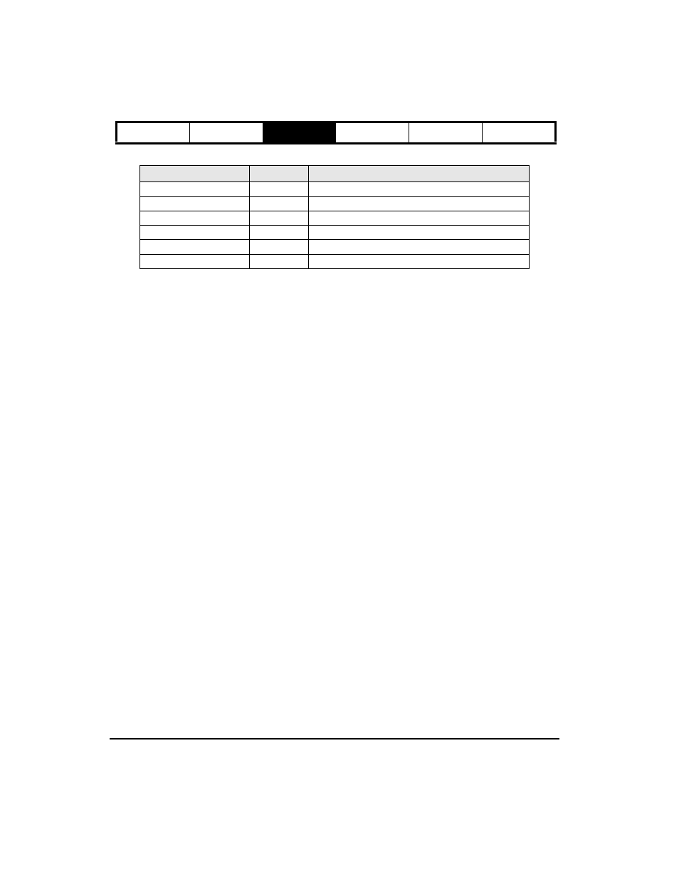
Function
Pin Numbers
Electrical Characteristics
Encoder Out
1, 2, 3, 9, 10, 11
Differential line driver output (RS 422)
Diagnostic Output
7, 15
± 10 Vdc 10 mA maximum analog diagnostic, ref. to pins 6 and 14
Diagnostic Output Common
6, 14
0.0 V, 10 ohms away from PE. 0 ohms away Logic Common (pin 8)
Pulse In
4
Single ended pulse input
Direction
12
Single ended direction input
Analog Command
5, 13
Differential; Analog Command Input