Motor power wiring, Nt and mg motors – Emerson 400518-01 User Manual
Page 31
Installation
19
Safety Information
Product Overview
Installation
Diagnostics
Options and
Accessories
Specification
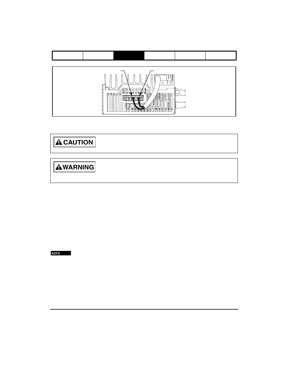
Figure 15:Shunt Resistor Connections showing SM-Heatsink DBR-1 Kit
Motor Power Wiring
The following paragraphs provide details of motor connections. When motor power cables are long, 100ft. [30 m], a
ferrite (Control Techniques p/n 157016-13, Steward p/n 28A3851-0A2 or equivalent) installed on the three phase
conductors but not the shield, near J1 can significantly reduce high frequency switching harmonics that in some
cases can cause communications errors. Maximum cable length is 200 ft [60 m]. J1 terminals are suitable for one
18 AWG to 14 AWG or ISO 0,75 to ISO 2,5 stranded conductors. The ground/shield terminal may contain the shield
and ground conductors together if each is 16 AWG or ISO 0,75 or ISO 1,5. Otherwise a ferrule must be used to crimp
both connectors together.
NT and MG Motors
NT and MG motors are equipped with up to three male MS (Military Standard) connectors, one for stator
connections, one for encoder connections and one for the brake (if so equipped).
Stator connections from the drive to the motor are made with the CMDS or CMMS cable have a female MS style
connector on the motor end and four individual wires and shield that connect to the motor power connector on the
front of the drive.
The motor ground wire and shields must be run all the way back to the drive terminal and must not be
connected to any other conductor, shield or ground except the enclosure wall for EMC.
Do Not make any shunt resistor connections to B-.
Shunt connections are at main voltage potential. Components connected must be rated for the voltage and
selected for safety. The external shunt resistor must have protection for a failed ON state of the shunt control.
B+PE
SHPE
B-
B+
SH